CPU Mining is back! A complete how to guide and profit analysis for Verium mining on a farm of single board computers - Part 2
Introduction
This is the second on three articles on profitable Verium CPU mining. The first part provided an overview of Vericoin and Verium, looked at options for mining hardware and their profitability. The conclusion was that Odroid XU4s (referred to as XU4 from now on) provided the best profitability from comparison of both initial purchase price to hash rate and hash rate to power consumption. This part therefore looks at how to build a basic miner (scaled up to 40 XU4s) right from a list of parts to a fully working miner. It has been written to make it accessible to all, and no knowledge of the hardware, software or operating systems will be assumed. The next part is intended to look at how to take the basis miner described in this article and use Docker Containers and Docker Swarm to manage all the computers.
System Overview
Figure 1 below shows the complete system block diagram for the 40 XU4 miner. Some of the rest of this overview might start sounding a bit technical, but I will provide step by step instructions on how to do this and for those just wanting a working miner without the description then just jump to these instructions in the next section!
As covered in the last article some home routers don't cope well with multiple WiFi clients, and most have around 4 wired ethernet ports on them. Given these limitations this miner has been designed around a Raspberry Pi 3 (referred to as “Pi3” from now on) that provides the miners link to the outside world (via its Wifi connection), with all the XU4s being on a private wired network controlled by the Pi3 via its wired ethernet connection.
To perform these functions the Pi3 runs a Dynamic Host Configuration Protocol (DHCP) server (to allow all the XU4s to be assigned Internet Protocol (IP) addresses and a Domain Name System (DNS) server to allow easy use of host names for the XU4s instead of editing the hosts file on every machine. The Pi3 also provides routing functionality to both allow direct connections into each of the miners for debugging from my main computer (instead of logging into the Pi3 and going from there), but also to allow the XU4s access to the internet to download updates etc. The final function that the PI3 provides is to host the Verium wallet software, which provides the link to the Verium network and provides the XU4s with mining work to do (again more on that later!)
The Pi 3 was chosen as the controller for three reasons over another XU4 - 1) it has built-in Wifi, saving buying a WifI dongle, 2) Price / performance, the controller doesn’t need the performance of an XU4 (with 40 clients the Verium wallet uses ~15% of the Pi 3 CPU) and the Pi3 is half the price, 3) related to two - I had already bought a Pi 3 to do performance tests on as per the last article!
A couple of standard unmanaged 10/100 Mbps (read inexpensive) switches provide 48 ports of physical network connectivity, gigabit speed is not required in this application and so it would add unnecessary cost to the switches. Moreover the Pi3 doesn’t have gigabit ethernet anyway.40 XU4s provide the mining grunt by running Verium mining software that communicates with the wallet software on the Pi3. 4 off 40A 5v DC power supplies provide the juice to power the XU4s and the Pi3 via a set of custom power leads.
This entire setup is mounted on an MDF base plate using a combination of threaded bar and spacers for the Pi3 and XU4s, good old velcro to hold down the power supplies / switches and a large number of cable ties to neaten everything up and make sure there is good airflow in the system.
The rest of this article is split up into how to get each of these elements up and running and then how to bring them together into a working system. The base plate will be covered first so that all the other bits can be integrated onto it as they are completed. A complete Bill of Materials (BoM) is provided at the end. For those wishing to make smaller scale miners then the instructions can still be followed, but just using the parts that you need. Single miners can also be made by moving the Verium wallet software onto one of the XU4’s and mining to the localhost address.
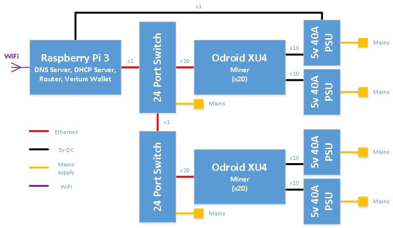
Figure 1 - System Block Diagram
Baseplate Construction
These baseplate instructions assume that the items used to build the miner are as per the BoM at the end of this article. If different parts are being used that are different sizes then this instructions will have to be adjusted accordingly. It also assumes that you are building a 40 XU4 scale miner. If you are not planning on having that many XU4s to start off with then it doesn’t hurt to make the baseplate so that the miner is scalable later - it’s only a few extra holes to drill!
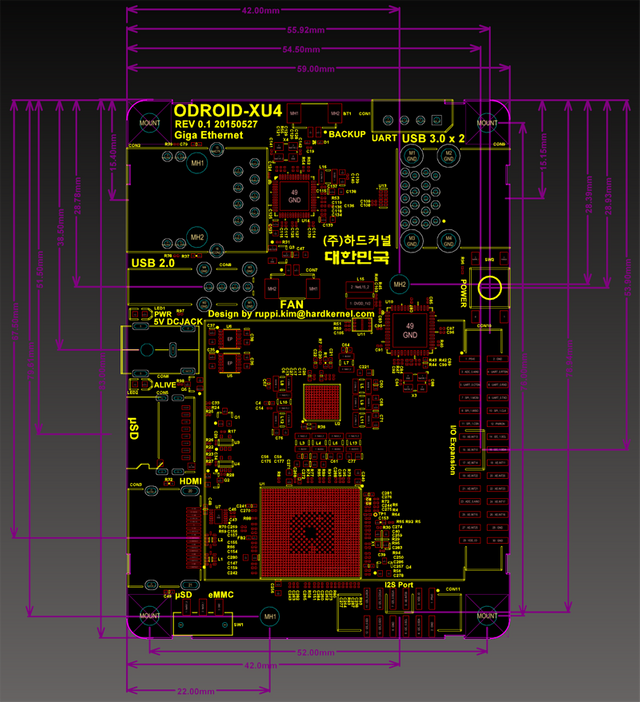
Figure 2 shows the baseplate layout and the hole positions and sizes that need to be drilled into it. I used a piece of 18mm MDF for my baseplate (mainly because it was in the garage!) but something that thick or thicker is probably a good idea as the finished miner is pretty heavy. The RPi3 can be put roughly where it is on the baseplate - the easiest way is to use its holes as a template, just make sure the USB power cable won’t foul any of the XU4 mounting posts and you’re good to go. The XU4 mounting information can be found below in case you want to make a different layout:
I couldn’t find any 3mm insert nuts so went for a glue in method instead as they aren't really load bearing. If you can get hold of 3mm insert nuts then can use them instead with appropriate adjustments in hole sizes.
As I didn't want the 3mm threaded bar holes to go through the board I used tape wrapped multiple times round the drill bit about 12mm from the end to get them the right depth. Apart from that just drill the holes and tidy up any messy bits where the drill bit breaks through. Be careful to be accurate on the hole locations though as having them off by too much will cause issues mounting the XU4s / Pi3 as the holes won’t line up.

Figure 2 - Baseplate Layout
Step 1.1: Cut out a piece of MDF as per the dimensions in Figure 2.
Step 1.2: Drill all the holes in the MDF as per Figure 2.
Step 1.3: Screw the M6 insert nuts into the 8mm pilot holes (using an allen key) on the baseplate for the power supply riser board supports.
Step 1.4: Cut 4 of the 1m lengths of 3mm threaded bar into 320mm lengths, and keep the ~40mm spare pieces. The 12x320mm lengths are for for mounting the XU4s on the left hand side (looking from the power supply end of the baseplate), and the 4x40mm lengths are for mounting the Pi3.
Step 1.5: Cut the other 4 1m lengths of 3mm threaded bar into 300mm lengths and discard the spare pieces. The 12x300mm lengths are for mounting the XU4s on the right hand side.
Step 1.6: Cut 4 150mm lengths of 6mm threaded bar. These are used to hold the power supply riser board in place.
Step 1.7: Thread a 3mm nut onto each of the 24 lengths of threaded bar until it is about 15mm from one end. Make sure that a nut can be put on the other end as well, but then take it off again. Cut ends are sometimes tricky to get the nut onto, if it won’t go then thread the nut from the other end and off the end that wouldn’t work to clear the thread out.
Step 1.8: Squirt some No More Nails (or suitable equivalent) into each of the first four holes for the 3mm threaded bar and insert the one of bars into each of the holes (nut end down). Push it in as far as it will go then thread the nut down to be level with the board (i.e. in the No More Nails glue) to give it a bit more strength. Repeat for all the other 3mm threaded bars, remembering 300mm lengths on the right hand side and 320mm lengths on the left hand side (when looking from the power supply end of the baseplate).
Step 1.9: Thread a 6mm nut onto each piece of 6mm threaded bar until it is about 15mm from one end. Make sure another one can go on the other end (as per Step 1.7 above).
Step 1.10: Screw one of the 6mm threaded bars (nut end down) into each of the insert nuts until the nut on the bar touches the insert nut, and then tighten the nut on the bar onto the insert nut using a spanner to lock the bar in place . Repeat for all the other 6mm threaded bars.
Step 1.11: Thread a 6mm nut onto each of the the 6mm bars until it is about 100mm above the baseplate. This will provide the support for the power supply riser board so make sure each of the nuts is level with each other.
The finishes the baseplate and now it just needs to be left for the glue to set. I left mine overnight as the bars get a fair bit of wiggling when the rest is assembled onto them so wanted the glue fully dry.
Network Switches and Power Supplies
Now that the baseplate is finished the rest of the miner can start to be assembled onto it.
First to go on are the network switches. I used two TP-LINK 24-Port 10/100 Mbps switches, specifically model number TL-SF1024D which can be bought for ~£30. The switches aren’t goign to be heavily loaded, no management features were needed for this very simple network but a decent number of ports were needed cheaply. This lead to the TP-LINK switches which ticked these all the boxes, seemed to have decent reviews and is passively cooled. Two 24 port switches were selected rather than one 48 port switch to make network cabling easier by stacking the switches on top of each other, one facing the left hand side bank of miners and the other facing the right hand side bank.
Each switch is simply fixed with double sided sticky back velcro.
Step 2.1: Stick the hooks and loop sides of the velcro together and cut off eight squares.
Step 2.2: Peel off one side of the backing and stick one square in each corner of both of the switches and press down.
Step 2.3: Peel the other backing off the velcro squares on one switch and stick it to the baseplate in the space marked for the switch and press down, making sure the ports are facing the right way - looking from the power supply end of the baseplate the ports must face to the right hand side of the baseplate.
Step 2.4: Mount the other switch directly on top of the first one, so peel off the backing and stick that one down with the ports facing the opposite side, i.e. to the left when looking from the power supply end. Now plug in the power cables (they will be tricky to get in later if you don't believe me!) and leave them hanging over the edge of the board.
The power supplies are mounted next. Each XU4 is rated at 4A, this includes power to run USB peripherals as well, but this application will also be running the CPU pretty hard and a stable power supply is needed. With 40 XU4s that means ~160A of 5V power is needed. The Pi3 power needs is in the noise compared to this but is somewhere in the region of 2A.
A number of power supply options were looked at, from using the individual wall-wart adapters that came with the XU4s (too many plug sockets and not as efficient as larger supplies), through PC ATX power supplies (nominally efficient, but most of the power rating is on the 12V rails so hard to get into the best efficiency range just drawing from the 5V rail and DC-DC converters to step the 12V down to 5V are expensive), finally settling on 5V switch mode power supplies as the best price / efficiency / size answer.
After looking through various suppliers websites and spec sheets the LRS-200-5 supply was picked. This gives 40A of 5V at 87% efficiency for less than £30, with free air cooling, i.e. no fan. Higher current rating supplies are available but the price per amp is less favorable and they start requiring active cooling (every fan uses power!). With a 40A rating 4 of these supplies are needed for this miner, powering 10 XU4s each, and one also powers the Pi3.
It should be noted that these are semi-enclosed power supplies that are designed to be included in equipment and so it’s pretty easy to poke things into the live parts, and the mains input is via exposed terminal block so also easy to touch. This means that if you have children / pets about then some additional safety protection is going to be needed for these supplies unless it is certain that this miner is well out of reach - for adults just don't touch the mains terminals or poke stuff through the holes when they are powered up! With that said the supplies are mounted in exactly the same was as the network switches.
Step 2.5: Put one double sided sticky back velcro square on each corner of each power supply.
Step 2.6: Stick two to the baseplate with the terminal blocks facing each other.
Step 2.7: Stick the other two to the power supply riser board, again with the terminal blocks facing each other. The power supply riser should be left off at this stage as need to get to the terminal block on the lower power supplies to cable them up first.
Step 2.8: Connect the mains leads to each power supply (including an earth connection).
Step 2.9: Cable tie down via the hole in the baseplate and power supply riser board near the terminal block.
Step 2.10: Put a layer of electrical insulating tape over the exposed mains terminal block connectors to prevent accidental touching, but as above additional protection may be required depending on your circumstances.
Controller Configuration
For ease the Pi3 controller is configured off the base plate and then installed at the end once its all working. I’ve provided line by line instructions here to allow those less technical to follow them. Having said that I’m no expert on linux - the instructions have been collated and tailored from a variety of forums / websites (see references) - so any corrections better ways of doing this then please provide them, and I will update and credit you with the changes! I'm also assuming Windows is running on the machine that will be used to install everything from, but will link to the places for linux and mac instructions. The IP address of the Pi3 on your network is assumed to be 192.168.123.20 in all the commands in this section. When following this guide you will need to replace this IP address with the one your Pi3 has on your network - see Step 3.6 for getting the initial wired ethernet IP address, and Step 3.16 for getting the wireless ethernet address. Note that these will almost certainly be different, but both have been assumed to be 192.168.123.20 for simplicity of writing.
To get the controller up and running you will need a Pi3, a Pi3 power supply, a microSD memory card (8GB), a card reader that can take microSD cards, a computer to write the microSD card, a network cable, a spare port on your router/switch, a USB keyboard and display with a HDMI connection and suitable cable. If you don't have the USB keyboard and HDMI cable then you can use Step 3.5 to remote connect from your computer, it just involves poking around in your router to find the Pi3’s IP address first, so might seem a bit more complicated.
Step 3.1: Download a copy of the latest Raspbian Lite OS image (Jessie at the time of writing) from here https://www.raspberrypi.org/downloads/raspbian/ to your computer and note where its put. Once downloaded go to that folder and extract it, by right clicking on it and selecting “extract all”, keep the default folder (or put it where you want the image) and click extract. You should now have an image (.img) file in the folder.
Step 3.2: Download Win32DiskImager from here https://sourceforge.net/projects/win32diskimager/. Run the installer, click next, accept the license agreement and click next, leave the install location as the default and click next, leave the folder as the default and click next, leave the desktop icon box ticked and click next, click install, untick the “view readme” checkbox and click finish. You should now have a running Win32DiskImager programme. If you get an error that’s probably because the programme needs admin privileges to run, so click ok on the error, locate the Win32DiskImager icon on the desktop, and double click to run it, click yes on the dialog box that appears and you will be up and running.
Step 3.3: Insert the microSD card into the card reader, and plug the card reader into the computer. A new drive should show up in windows explorer, make of note of the drive letter. Now switch to Win32DiskImager and select that drive letter in the “Drive” drop down box in the top right of the programme. Now select the folder icon next to it and browse to where you extracted the operating system image to in Step 3.1, select the file and click “open”. Now click “write”, accept the warning and wait for it to finish. Now eject the card reader by clicking the “safely remove hardware” icon in the task tray area, select the card reader and then select “eject”. You now have a micoSD card with the operating system on it. For Linux and Mac - follow the instructions here: https://www.raspberrypi.org/documentation/installation/installing-images/README.md
Step 3.4: To connect to the Pi3 without having to use a keyboard and display you will need to use a Secure Shell (SSH) programme. PuTTY is my programme of choice which can be downloaded from here http://www.chiark.greenend.org.uk/~sgtatham/putty/download.html. There is nothing to extract or install this is just the programme you need ready to run. Linux and Mac already have SSH installed, which is accessed via the terminal.
Step 3.5: Insert the microSD card from Step 3.3 into the Pi3, plug one end of the network cable into the Pi3 and the other end into your router/switch, plug in the USB keyboard and connect up the HDMI cable to the display and Pi3 (if using), then plug in the power supply to the Pi3 and then plug the power supply into the mains supply. All being well you will now have working Pi3 - the red LED should be on (good power), the green LED should be flashing (microSD card activity) and some activity on the wired ethernet port LEDs. If you used an external display then skip Step 3.6.
Step 3.6: Log-in to your router. This can be done by typing in the IP address of the router into your browser, e.g. 192.168.123.1 or similar. The IP of your router can be found in Windows by the following steps: press the windows key + R, then type “cmd” without the quotes in the “Run” dialog box and press OK, then type “ipconfig” without the quotes and press enter. The router’s IP address if the one under the “Default Gateway” section of the information listed. Other operating systems instructions are here http://www.howtogeek.com/233952/how-to-find-your-routers-ip-address-on-any-computer-smartphone-or-tablet/. Enter the username and password for the router (probably written on the bottom of the router if you have been particularly insecure and not changed it…). Look for the section that shows the connected devices (under “Attached Devices” on my netgear router) and look for the device named “raspberrypi” and make a note of its IP address. Open up PuTTY (see Step 3.4) and type this IP address into the “Host Hame (or IP address)”, make sure “Port” is 22 and then click “Open” to connect. For Linux and Mac open a terminal window and type:
ssh [email protected]For all connections you will now be asked to confirm the identify of the machine with a message something like the following (the key fingerprint will be different for your machine):
The authenticity of host '192.168.0.20' can't be established.


RSA key fingerprint is f9:9b:06:11:75:d4:1f:d1:3c:51:0d:22:4a:13:ff:9f.


Are you sure you want to continue connecting (yes/no)
Type:
yesStep 3.7: If you have connected to an external display you will have a prompt on-screen asking now for a username and then a password, if you have used PuTTY then you will also be asked for a username and then a password, if using SSH from Linux or Mac you have already passed the username in the ssh command so will just be asked for the password. The default username and password for the Pi3 are “pi” and “raspberry” respectively (without the quotes), so enter them as requested and confirm identity as per Step 3.6. You are now logged into your Pi3.
Step 3.8: Next is to update the Pi3 to the latest versions of everything that is already installed. Type:
sudo apt-get update && sudo apt-get upgrade -y && sudo apt-get dist-upgrade -f -yThe first part of this command “sudo” runs this as the superuser, i.e. will the elevated privileges needed and “apt-get update” gets the list of latest versions of all the packages (similar to getting the latest installer files on windows) that are available. The “&&” tells the machine to execute the next part if, and only if, the previous one has completed successfully. The next part “sudo apt-get upgrade -y” uses the refreshed package list to update everything that is already installed to the latest version, and the “-y” on the end removes the yes/no prompt about upgrading. The last part “sudo apt-get dist-upgrade -f -y” handles any changed dependencies between packages that are needed when upgrading, with the “-f” forcing any missing packages and the “-y” doing the same as before.
Step 3.9: Depending on how you have your network configured / who has access to it you may want to set up a firewall on the Pi3 to limit connections to/from it. A guide for this is here: https://wiki.debian.org/Uncomplicated%20Firewall%20(ufw) but has been left out of this article for three reasons 1) to make it simpler, 2) a home setup with a firewall built into the router probably won’t need it, 3) network address translation is used and 4) it adds extra steps in debugging if things don't work. If it is needed then you should be ok getting it up and running!
The Verium wallet is installed next as it needs time to download and process the blockchain - this can be quite slow on the Pi3 because of its limited resources so is done first to get it up and running as quickly as possible.
Step 3.10: The build environment and dependencies for building Verium are installed by typing:
sudo apt-get install build-essential libboost-dev libboost-system-dev libboost-filesystem-dev libboost-program-options-dev libboost-thread-dev libssl-dev libdb++-dev libminiupnpc-dev libboost-all-dev libqrencode-dev freeglut3-dev git -y“apt-get install” attempts to install all the packages (think of it as a compressed collection of all the files required for a particular programme) that are listed after the command. It is left to the reader to work out what all the packages installed here do, simple google searches will turn the information up if you’re interested.
Step 3.11: The source for the Verium wallet can now be downloaded by typing:
git clone https://github.com/VeriumReserve/veriumStep 3.12: Once that has completed it can then be built by typing the following commands:
cd verium/srcmake -f makefile.unixThis will take a while to build, there should be no errors but will be a few warnings which can be safely ignored. If there are errors then make sure all the preceding steps have been carried out correctly and retry. Once it’s finished type:
lsWhich lists all the files in the directory. “veriumd” will be one of the files in there if all has gone well. This is the Verium “daemon” which means that it is a programme that can run as a background process without direct user control.
Step 3.13: The Verium configuration file is created next by typing:
nano verium.conf“nano” is a text editor programme and the filename after it is the one that it opens for editing. In the editor type the following into the file, then save and exit by pressing ctrl-x, then pressing y and then pressing return:
addnode=vrmsupernode.vericoin.info


addnode=vrmsupernode3.vericoin.info


server=1


listen=1


daemon=1


rpcuser=veriumuser


rpcpassword=secret


rpcallowip=172.16.0.*


rpcallowip=192.168.123.*


rpcallowip=localhost
The two “addnode” lines give a couple of starting nodes to allow the wallet to start synchronising. “server” tells the Verium wallet to accept JSON-Remote Procedure Calls (RPC) (http://www.jsonrpc.org/ if you want unnecessary detail!). “daemon” runs the wallet as a daemon, i.e. a background task. “rpcuser” and “rpcpassword” are the username and password that are needed to communicate with the wallet via RPC commands - these can/should be changed (and arent the same as the ones I used!), just remember what they are as they will be needed when setting up the miners later. The two “rpcallowip” lines provide permission for IP address ranges to access the miner via RPC, all other IP addresses will be denied. The “172.16.0.*” entry provides access to all the miners as this is the IP address range that will be configured for them later. “192.168.123.*” provides access for the XU4 as it is being built and tested, this line can be removed or commented out later or left in. “localhost” provides access from the Pi3 to allow checking of the status of the wallet from that machine.
Step 3.14: Now the wallet is built and has a configuration file the wallet can be started by typing:
./veriumdA message should be returned saying “server starting”. The wallet will now connect to the network and download the blockchain. As stated above this can be very slow on the Pi3. Progress can be checked by looking at processor load by typing:
topThe “top” command shows all processes running, ordered by CPU usage (by default). The process “veriumd” should be using approximately 100% CPU, shortly after starting. If it is things are looking good, so exit top with ctrl-c. Progress on loading the blockchain can then be examined using the following command:
./veriumd getinfoThis sends the RPC command “getinfo” to the verium wallet, and prints out the response. This command might be slow to respond whilst the blockchain is downloading, and initially may just return an error message. If it does return an error message, but “veriumd” is using CPU as above then just wait a while and try again.
Whilst waiting for the blockchain to download the rest of the Pi3 can be set up.
Step 3.15: Now the wallet needs to be setup to automatically start up at power-on, just in case the Pi3 crashes or reboots unexpectedly. This is done by adding commands to the rc.local file. The commands in this file are run at startup. Edit rc.local by tying:
sudo nano /etc/rc.localIn the editor add the following line to the file just above the line that says “exit 0”, then save and exit by pressing ctrl-x, then pressing y and then pressing return:
sudo -H -u pi /home/pi/verium/src/veriumdCommands started from rc.local are, by default, run as the root user and that isnt needed or desired for running the Verium wallet software. The command “sudo -H -u pi” tells the system to run the command as the user “pi” and to set the home directory for the user (which isn’t configured at this point in the Pi3 boot sequence). “/home/pi/verium/src/veriumd” is the file path to the verium software that is to be executed.
Step 3.16: As stated above WiFi will be the method used to connect the Pi3 to the internet and the wired connection will be the one used to connect to the XU4s so now the WiFi needs to be set up and then the Pi3 internet connection can be swapped over to that so the blockchain can carry on downloading whilst the wired network is set up. These instructions are copied from here https://www.raspberrypi.org/documentation/configuration/wireless/wireless-cli.md which has explanations of what the commands do and limited trouble shooting. So see there for more details. Otherwise the commands below can just be followed, Start by type the following command to list the WiFi networks that are in range:
sudo iwlist wlan0 scanYour WiFi network should be in this list under on of the “ESSID” entries. Next the confg file that controls connections to WiFi needs to be edited to include this network, so type:
sudo nano /etc/wpa_supplicant/wpa_supplicant.confTo the end of this file add:
network={


   ssid="your_wifi_network_ESSID"


   psk="Your_wifi_password"


}
Where your_wifi_network_ESSID is the name of your network and Your_wifi_password is your WiFi password. The quotes around these items stay there in the file. Again this information is probably written on the bottom of the router if it hasn’t been changed. Save and exit the file by pressing ctrl-x, then pressing y and then pressing return. The Pi3 should pick up the new settings in a minute or so or they can be forced by taking the WiFi adaptor up and down again by typing the following commands:
sudo ifdown wlan0


sudo ifup wlan0
Finally make sure the WiFi is connected by typing:
ifconfig wlan0In the output from that command if “inet addr” has an IP address next to it then WiFi is working. Make a note of this address as this will be the address that is used to connect to the Pi3 from now on. As stated above for this guide this is assumed to be 192.168.123.20 but this will be different for your setup, not least because this is also the address that the wired ethernet is currently using as well! Assuming WiFi is working then the wired Ethernet connection can now be disconnected. This will (obviously!) break the SSH connection, so SSH back into the Pi3 using the WiFi IP address and accept the new fingerprint as per Step 3.16. Now check that the wallet software has successfully transitioned to the WiFi connection by typing the following command twice and making sure that the “blockcount” in the output from the command goes up between each command or if this guide has taken a long time then the blockchain might be synchronised if the “blockcount” matches the block height here https://chainz.cryptoid.info/vrm/
~/verium/src/veriumd getinfoIn this command the “~” is shorthand for typing in the current user’s home directory, i.e. “/home/pi/”. If there are problems the easiest way is now to reboot as everything will start up automatically. So type and then SSH back in again after the Pi3 has rebooted:
sudo reboot Step 3.17: Now that the connection to the Pi3 is via Wifi the wired ethernet side of the network can be set up. To get this working a private network will be set up on the wired ethernet side to join all the XU4’s to and the internet connection on the WiFi will be shared to this private network. As covered in the System Overview section this needs a DHCP server, a DNS server and routing to be set up between the two networks. This section is adapted from this guide here https://www.raspberrypi.org/forums/viewtopic.php?t=132674. First up is the dnsmasq utility which is used to provide DNS and DHCP functionality. Full info on this utility can be found here http://www.thekelleys.org.uk/dnsmasq/doc.html. To install type:
sudo apt-get install dnsmasq -y Now the IP address of the wired ethernet connection is made static (fixed) so that the XU4’s that will be clients of the DNS and DHCP servers will always have the same address to use (when doing renewals of the lease of their IP address etc. but getting into unnecessary details!). So edit the network interfaces file by typing:
sudo nano /etc/network/interfaces Now scroll down this file until you find the line describing the wired interface. This will be something like “iface eth0 inet dhcp”. This line currently tells the Pi3 to use DHCP for the wired ethernet interface (represented by “eth0”) to automatically get an IP address for it, which isn’t what is needed so comment out this line by adding a “#” to the beginning of the line. The makes any line starting with it a comment. Now add the following lines to the file straight after the line just commented out:
allow-hotplug eth0


iface eth0 inet static


   address 172.16.0.1


   netmask 255.255.255.0


   network 172.16.0.0


   broadcast 172.16.0.255
The first line “allow-hotplug eth0” tells the Pi3 to start the interface when an event is detected, such as when the cable is plugged in. The next line “iface eth0 inet static” tells the RPi3 to use a static IP address for the wired interface, and the next four lines set the configuration of interface. “address 172.16.0.1” is the actual IP address to be used 172.16.0.1, “netmask” defines the subnet or the range of IP addresses that the RPi3 can communicate with, in this case 172.16.0.1 to 172.16.0.255 and “broadcast” defines the broadcast address which means that anything sent to that address is sent to all the hosts on that subnet (as defined by netmask). Google “ipv4 networking basics” or similar to get more information. Save and exit the file by pressing ctrl-x, then pressing y and then pressing return.
Next up is setting up dnsmasq, so make a copy of the original dsnmasq configuration file by typing:
sudo mv /etc/dnsmasq.conf /etc/dnsmasq.conf.origThe “mv” command is used to moves the file to a new one in the same place, just with a different name. Now a new configuration file is created and opened for editing by typing:
sudo nano /etc/dnsmasq.confAdd the following lines to the file - the comments after the “#” on each line explains what each lines does. Save and exit the file by pressing ctrl-x, then pressing y and then pressing return.
interface=eth0               # Use interface eth0


listen-address=172.16.0.1    # Explicitly specify the address to listen on


bind-interfaces              # Bind to the interface to make sure we aren't sending things elsewhere


server=8.8.8.8               # Forward DNS requests to Google DNS


domain-needed                # Don't forward short names


bogus-priv                   # Never forward addresses in the non-routed address spaces.


dhcp-range=172.16.0.2,172.16.0.254,12h        # Assign IP addresses between 172.16.0.2 and 172.16.0.254 with a 12 hour lease time
Next is setting up routing between the WiFi and wired ethernet links. So open the configuration file by typing:
sudo nano /etc/sysctl.confFind the following line and uncomment it by removing the “#” at the beginning of the line to make it look like the line below. Save and exit the file by pressing ctrl-x, then pressing y and then pressing return.
net.ipv4.ip_forward=1This line tells the Pi3 to route, i.e. forward, any packets of data that it gets on one of the network interfaces that doesn’t have an addresses on that network out over the other interface. In this example the WiFi interface has the address 192.168.123.20 and a netmask of 255.255.255.0, which means that valid addresses for this interface are in the range 192.168.123.1 to 192.168.123.255. If a packet with an address of 172.16.0.3 arrives at the WiFi interface then the Pi3 will forward that packet out over the wired interface to see if the right destination can be found on that network.
Next is setting up iptables to do network address translation, so type:
sudo iptables -t nat -A POSTROUTING -o wlan0 -j MASQUERADE“iptables” is a firewall utility that is used here to do network address translation. “-t nat” selects the network address translation table, “-A POSTROUTING” appends to the POSTROUTING chain, “-o wlan0” selects the output adaptor as wlan0, i.e the WiFi adaptor and “-j MASQUERADE” jumps to the MASQUERADE target which looks up the IP address of the wlan0 each time and translates the packet to that address, doing port translation as required, so that each of the IP addresses on the wired ethernet side can reach the WiFi network by using that same IP address as the WiFi adapter. Ports are translated so that each packet coming back in can be appropriately routed back to the right IP address on the wired network, e.g. if 172.16.0.3 is communicating on port 4567 and 172.16.0.4 is also communicating on port 4567 packets for each will be routed to 192.168.123.20 (the WiFi interface) and then have their IP addresses changed to be 192.168.123.20 and their ports changed to be unique, e.g. packets from 172.16.0.3 use port 4567 and those from 172.16.0.4 use 4568, so that when packets come back on 192.168.123.20:4568 iptables knows to route them back to 172.16.0.4:4567
Next up is configure the iptables settings to load on reboot (as they are only stored in memory currently) by first typing:
sudo sh -c "iptables-save > /etc/iptables.ipv4.nat"This runs the “iptables-save” command which writes to stdout, the “>” pipes, i.e. writes, this to the file “/etc/iptables.ipv4.nat”
Then a hook file is created to restore the state of iptables on reboot, type:
sudo nano /lib/dhcpcd/dhcpcd-hooks/70-ipv4-natIn the file add the line below then save and exit the file by pressing ctrl-x, then pressing y and then pressing return.
iptables-restore < /etc/iptables.ipv4.natTest the configuration by rebooting the RPi3 by typing:
sudo reboot When the Pi3 comes back up anything plugged into the wired ethernet should have internet access via the WiFi connection. Test it with a computer plugged in, or wait to test with an XU4 in the next section.
Step 3.18: The last bit to set up is a utility called “pssh” or parallel ssh. This allows multiple linux hosts to be passed the same command in parallel via ssh. Very useful when there are 40 XU4s that need to be controlled! First up is installing the python package manager (pip) so type:
sudo apt-get install python-pip -yNext up install pssh itself, so type:
sudo pip install psshThat is now all ready to go. A hosts file will be set up later to allow this to be used, but the XU4 host names will be configured in the next section.
The second half of this article can be found here:
Join us at our slack channel for help and more info http://slack.vericoin.info/
Awesome Job!
Impressive!
@bitworkers
WOW, great Job. I just start on this topic and your post was a real good read...