pbjtech | IoT5500 LanJack Ethernet Module + Network CPU |

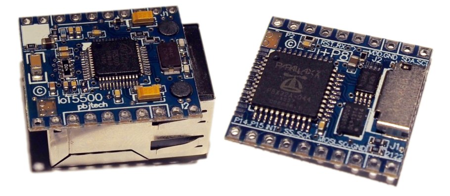
The Internet of Things embedded Ethernet connectivity module IoT5500 comes in a very compact footprint, barely any larger than the Ethernet socket. As the base module it can be connected directly to a host system via SPI or with the optional CPU+SD thin-stack module becomes a network server offloading the burden of network operations as a smart peripheral. Even more importantly too is that is very cost effective even when compared to many serial to Ethernet only solutions alone.
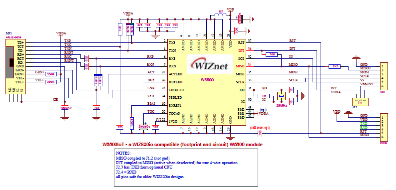
Based on the WIZnet W5500 hard-wired TCP/IP Ethernet chip the module is both compact and easy to interface to via SPI and is footprint compatible with the older W5200 based WIZ820io module.
IoT5500 Features
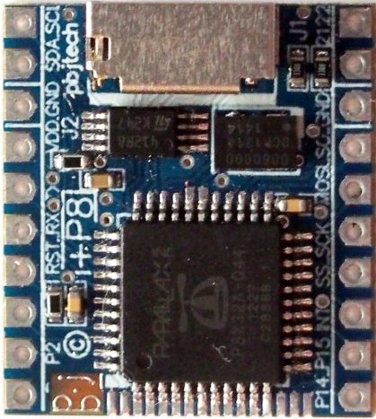
| +P8 CPU module
|
LINKS: Short video demonstration Ordering information
Description
The IoT5500 is a complete Ethernet module that supports 8 hard-wired TCP/IP sockets as well as UDP and IPRAW etc. External hardware can interface to this module over SPI but client or server software has to be implemented by the host. To supplement the base IoT5500 module there is the +P8 companion module which attaches to the bottom of the IoT5500 and provides network servers and file-system etc. In this mode the IoT5500+P8 combo can provide full stand-alone networking services or it can also connect to a host CPU via serial or I2C bus as a smart network processor. In this serial mode since the +P8 is handling all the protocols then all that is required of the external CPU are simple commands and data which can be accomodated at lower baud rates to suit 8-bit CPUs.
Although the +P8 module is designed mainly to offload the networking and filesystem from the host CPU, it can also operate stand-alone as a datalogger or a simple IoT interface. There are up to 9 extra I/O available on the pin headers plus another 11 I/O from the fine-pitch half-holes.
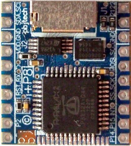
The rear edge of the CPU module also includes P8 to P13, GND VDD, P8RST as half-holes at the same pitch as the QFP of 31mils.
Design rationale
So the Prop add-on can communicate with a host using serial or I2C or half-duplex via P2 etc plus this means that since we have this dedicated Prop handling the protocols and filesystem etc that the host system has all it's memory available rather than being filled to the brim. The Telnet protocols can be used to communicate directly with the host if necessary while the FTP and HTTP protocols can operate independantly while the host CPU can access the FAT32 SD filesystem using simple serial commands. Alternatively the module can be put into datalogger mode where it grabs the serial stream and looks after logging of the information into the filesystem while remote sites can access the data as FTP, TELNET, or as a web page. There is some work being done with AJAX stuff too for dynamic content but leveraging the runtime Forth kernel rather than slow javascript which would be impractical for smaller systems.
File and datalogging operations require time-stamping but rather than wasting room with an RTC + battery, the design choice was logical, use the network interface to implement SNTP time protocols which synchronizes the virtual RTC. For visual indication external LEDs may be connected directly to P21 and P21 through to ground as there are resistors built-in on the +P8.
In terms of more general operation the +P8 module is not meant to be a be-all as it has it's job cutout with the Ethernet and filesystem and also because it is designed to be compact then there are some but not all I/O available.
Just plug this module into a Prop Quickstart or breadboard and have some fun in any language you choose. BTW, since I run Tachyon Forth on the Prop you can easily send "commands" or "scripts" which are just Forth words strung together, even make a "macro" out of them

An optional 16Mbyte Flash can be fitted which is accessed in the same manner as the microSD FAT32 file system using simple C: and D: drive select commands to select between either "drive". If only one storage memory exists though then it will default to C: drive.
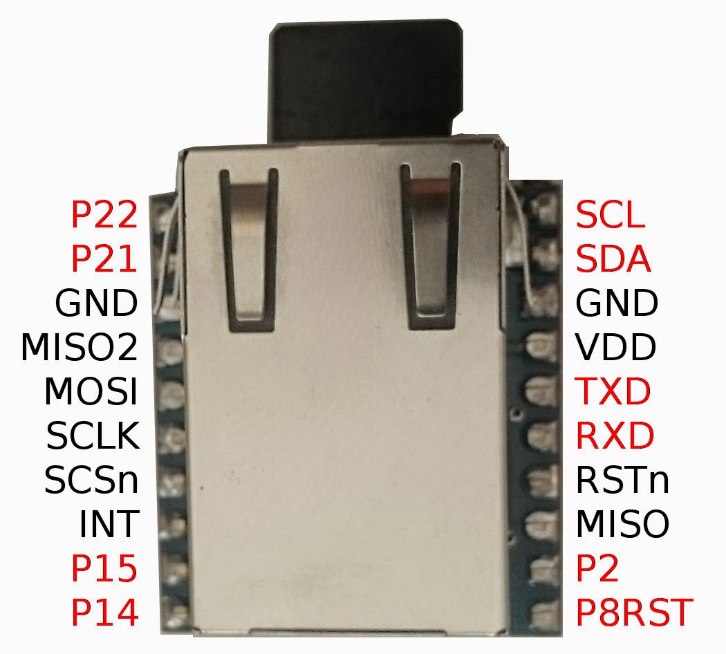
Hardware connections
As an Ethernet only module the IoT5500 has been designed to be footprint compatible with the WIZ820io and in case some pins have been repurposed they can still be safely connected to a WIZ820io socket. These signals are standard W5500 signals as described in the datasheet for this part with the addition that MISO is also available on the same side as the rest of the SPI signals except it is safely isolated via a 2K2 resistor in case it is connected as a WIZ820io module. The module also includes a 10K resister from the INT pin to the MISO so that systems can cut down on the number of I/O required and just monitor MISO when the chip is deselected for an interrupt.
With the addition of the +P8 module the W5500 signals are controlled by the P8 and the system interface is via the P8's I/O such as the RXD/TXD serial port, the I2C pins, or by other means through software. When the P8 is placed in reset by pulling the P8RST line low then it is possible to access the W5500 directly.
Mounting
For production purposes where this module will be used with a custom PCB it is possible to introduce an edge cutout on the PCB where the module slots into so that the magjack is level with the surface of the PCB. In this use the pins are not needed and instead connection may be made across the jumper pads between the module and the PCB to keep the module as flush as possible. The microSD is designed to jut out underneath the magjack as this would be where the edge of the enclosure is situated and so the microSD can be removed if required without opening the enclosure.
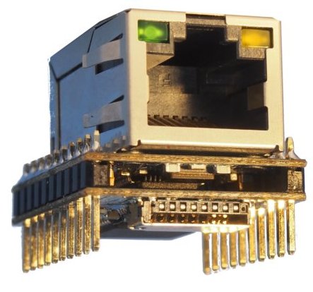
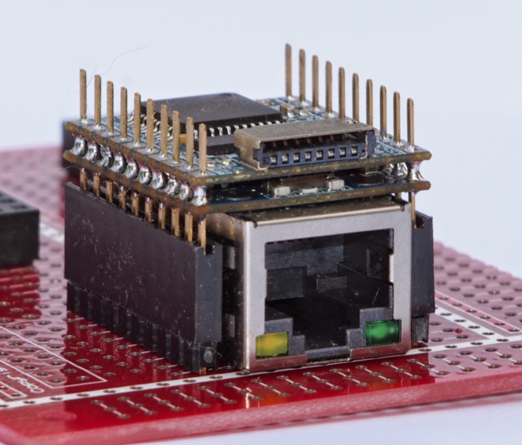
Low Profile
New VS Inverted Vertical stack mounting option allows the module to be mounted flush to the pcb for a very low profile minimal footprint Ethernet network server module.
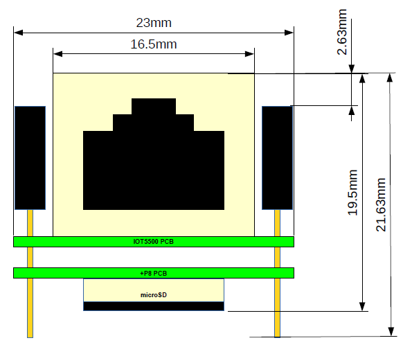
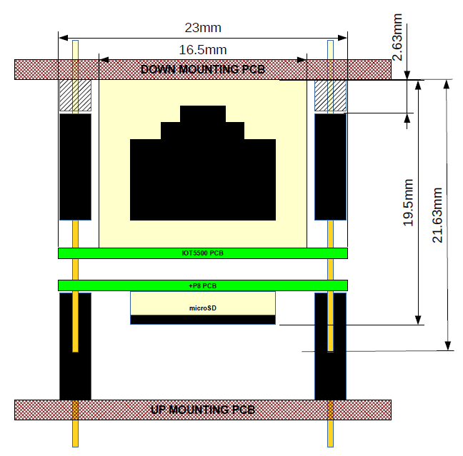
MECHANICAL DIMENSIONS
Front view of the VS mount option which allows either "up" mounting with the socket on the top or "down" mounting with the socket flush to the mounting pcb.
Two rows of 0.1" pin spacing x10 pins with rows spaced 0.8" (20.32mm) apart.
Up mounting total height from mounting pcb is 25.4mm
Down mounting total height from mounting pcb is 21.63mm (or 19.5mm with pins trimmed)
Total length front to back is 25.78mm
FIRMWARE
Configuring ports
Ports and parameters can be configured via the serial command channel or via the web interface by navigating to the config page.
Serial port
A full-duplex serial port is available for communicating with a console or host system via RXD and TXD. These signals are standard 3.3V logic and are not 5V tolerant. If it is desired to connect to 5V logic then a 3K3 resistor should be used in series with the RXD and if necessary a HCT logic gate or other circuit can boost the 3.3V TXD signal to 5V.
The default baud rate for this channel is 115200 baud 8N1 but can be changed and locked in easily. All commands are in whitespace seperated text delimited by a <CR> while any <LF> characters are ignored.
Ethernet to Serial mode
In Ethernet to serial mode the maximum throughput at present is 115.2k baud and although this may be improved upon the maximum is limited by the SPI interface to the W5500. Multiple ports may be specified so that under software other GPIO lines can become high-speed serial channels.
Ethernet to MODBUS
This protocol may be specified on top of either plain serial or RS485 mode.
Ethernet to RS485
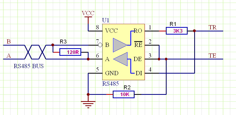
This mode may be used to communicate to an RS485 network via an external RS485 chip using the default port pins P14 and P15 as transmit enable (TE) and transmit/receive (TR) respectively. The TE will activate automatically whenever data is sent to be transmitted and release after the last character has been sent. Additional commands allow for transmit hold while line busy, packetization, etc. This RS485 mode also forms part of the MODBUS protocol that may be used on top of this driver. Additional ports may also be specifed.
RS485 CONNECTIONS
P14 | TE | RS485 transmit enable (/RE & TE tied together) |
P15 | TR | Transmit and receive data (tied together) |
RS485 CIRCUIT EXAMPLE
Ethernet to I2C mode
I2C bus devices may be connected up to SCL & SDA pins and accessed over Ethernet protocol using simple text commands and all data is sent as 2 hex bytes. Start and stop conditions are represented by S and P respectively. To read data back use the R command in this S<HEX>P format.
Example of reading 4 bytes from the EEPROM at address 0000:
Example | Description | Response |
SA00000P | S=Start, $A0 (device address write), 00 00 (memory address), P=Stop | A=Ack or N=Nak |
SA1RRRRP | S=Start, $A1 (device address read), R R R R (read 4 bytes, P=Stop | A=Ack or N=Nak |
For writing to I2C memory areas the Intel hex format can also be used after issuing the start and device address but instead of the raw address and data bytes a colon signifies that the data should be interpreted as a line of Intel hex data as in this example:
To write 16 bytes to a device at memory address $0000:
S0A:10000000003FC4046FF01000002E082EC47E0C2E9AP
To write 64 bytes to a device at memory address $0200:
SA0
:10020000E80AF219F10AFC19000B5A1ABE0E621A1A
:10021000C20E691AC60E6C1ACA0E6F1ACE0E721A68
:10022000D20E7B1AD60E8A1ADA0E961ADE0E9A1A99
:10023000E20E9A1AE60EA21AEA0EA91AEE0EB91AE0
P
Spaces and end of line terminators are permitted and are not sent so in the above example the 64 bytes of data would be written as one EEPROM page write.
Ethernet to NeoPixel mode
This mode works similar to the I2C mode in that all data is sent as hex bytes using S and P so that S will start buffering then P will transmit the buffer contents followed by a line idle.
Sockets and Port numbers
Skt | Port | State | Function(s) | Resource | Alternative |
0 | 502 | RS485/MODBUS | P14,P15 | ||
1 | 21 | LISTEN | FTP | Filesystem | |
2 | 30000-50000 | FTP DATA | Filesystem | Client port or alt HTTP | |
3 | 80 | LISTEN | HTTP | FIlesystem | |
4 | 10001 | LISTEN | Serial Port #1 or Telnet | RXD,TXD Console | |
5 | 10002 | Serial Port #2 | |||
6 | 10003 | Serial Port #3 or NeoPixel LEDs | P2 (half-duplex) | ||
7 | 10004 | I2C | SDA,SCL |
Serial & Console Commands
Commands may be transmitted to the +P8 serially in simple ASCII text format. Additionally new commands may be created over the serial link to build "macros" to suit the user application. Every subroutine and function by name is available although not necessary for normal operation although useful if new commands are created or simply for diagnostic purposes. Only a very short list of the main commands are summarised in this document however.
There is no hard fixed syntax although one or more whitespaces must be observed between all parameters and commands. The format is postfix as this is the natural processing of Tachyon Forth and is very efficient but also allows for symbols and calculations which may even be on preceding lines. As each parameter or number is received it is pushed onto a data stack which is then popped as needed by the command. For instance the SOCKET command will pop a number off the stack so this parameter must be passed before the command is executed which is why it is in the format "0 SOCKET". Symbols may also be created and used in place of these parameters, some are predefined also such as FTP and HTTP and TELNET for selecting sockets.
The default baud rate for this port is set to 115200 baud but can be changed at anytime with the BAUD command. Sending a break to the serial port will reset the Prop so only 2 I/O lines are every needed from the host and the Prop will revert back to the default baud rate on reset to prevent any incorrect baud rates from locking up the serial channel. An autobaud feature may be added later to automatically adjust as required however.
Preliminary Summary of Serial Commands (variable whitespace and <CR> termination <LF> redundant)
COMMAND | USAGE RESPONSE | DESCRIPTION |
FOPEN | FOPEN HOME.HTM ...opened at 0000.D7A8 ok | Opens the named file |
FILE | 1 FILE ok | Select one of four file channels 0 to 3 |
cat | cat <filename>...opened at 0000.D7A8 <crlf> <file data> ok | List the text contents of the file terminated with a ^Z and ok response |
ls ls -l | ls -l <directory listing> ok | List the directory with optional -l long format -rwxrwxrwx 1 502 500 376830 Nov 20 10:31 DRAGON1.JPG |
WRITEFILE | WRITEFILE <data> ^Z | Write all text data to the currently open file and terminate data mode when a ^Z is received |
RENAME | RENAME MYHOME.HTM to HOME.HTM | Rename the file (name must be in 8.3 format) |
SOCKET | 0 SOCKET | Select W5500 socket 0 to 7 to use (predefined labels can also be used such as FTP HTTP TELNET etc) |
TCP UDP IPRAW MACRAW PPPoE CLOSED | Select protocol for the current socket | |
SIP SUBNET GATEWAY | &192.168.0.40 SIP &255.255.255.0 SUBNET &192.168.0.1 GATEWAY | Set the IP parameters using IP notation and backup in EEPROM |
PORT! | 21 PORT! | Set the source port and backup setting into EEPROM |
CONNECT | CONNECT CONNECTING then --- CONNECTED | |
DISCONNECT | ||
SETLOG | 9600 8N1 #P2 NI SETLOG | Set P2 as the serial receive data for automatic text logging, 9600 8N1 and non-inverted |
LOGFILE | LOGFILE <name> | Select the file to use for logging |
sOPEN sCONNECT sLISTEN sDISCON sCLOSE sSEND sSENDMAC sSENDKEEP sRECV | Direct mode commands for W5500 socket | |
TO: | TO: pbjtech@gmail.com | Prepare SMTP email. |
SUBJECT: | SUBJECT: Testing email from IoT5500 | Set subject field |
MSG: | MSG: <text data> ^Z | Send text data to SMTP server as is and terminate data mode with a control Z |
POST | POST | Instruct SMTP server to POST this email |
IPSERIAL | <dest name> <port> IPSERIAL <data> ^Z | Connect to IP serial port transparently but terminate data mode on a control Z without closing the connection |
PLAY | #P14 PLAY <filename> | Play the WAVE file through the selected audio port P14 (RC filtered) |
PWM | 64 #P2 PWM | Set PWM on #P2 to 64/256 duty cycle (up to 32 simultaneous channels available @7.6kHz) |
BAUD | 2,000,000 BAUD | Change baud rate to 2M but don't lock it in so that it may revert back to the default 115200 after reset |
NETRTC | Force internal virtual RTC to update via the network | |
LOADROM | LOADROM EASYNET.ROM | Load a 64kB ROM file into the EEPROM - new firmware will take effect on reboot |
REBOOT | REBOOT | Reboot the system |
Servers
FTP and HTTP are supported although at present this is limited to one socket at a time for both. FTP may be initiated from a suitable client such as FIleZilla or even from a browser such as Chrome by preceding the URL with the ftp:// protocol specification.
RTC
A virtual RTC is maintained in software but this is synchronized with the network automatically on reboot using either a simple GET method to a known server or else SNTP protocol. If the network is not available then this action will continue to retry at short intervals until it has synchronized after which the synchronized will default to every hour. Since the virtual RTC is derived from the CPU clock it is very stable and along with network synchronization is very accurate. User input may set the time zone but otherwise the time is reported as UTC.
Data Logging
A common use for embedded systems with mass storage is to log data either from various sensors, or system messages, as well as from external sources. Typically a log file will be constantly growing as more data is appended to the file plus there is a need for automatic flushing of written data yet at the same time taking care not to overly stress the recording medium which in this case is Flash based SD with limited endurance. So care is taken to handle log data so that the FAT32 sectors especially are not overstressed. This means preallocation of clusters so that the FAT cluster table is not constantly being updated and the same applies to the directory where the file size would normally be updated. Timeouts are employed to flush data in RAM buffers to the storage and also much longer timeouts are used in updating the file size information. Mostly this information is tracked by terminating text files with a null so that the file size can be read on boot and also used when reporting file sizes over FTP without having to update the physical storage media.
This means that data can be sent to the module without any concerns about sector wear and FAT32 corruption if the media is unexpectedly ejected.
After the log file has been selected and the log mode parameters setup then any data received on the selected port pin will be logged accordingly. To switch back to command mode it is necessary to issue a <DLE> <ESC> sequence so therefore if this sequence is part of the data then it needs to be replaced with <DLE> <DLE> <ESC>.
Command channel logging procedures
Command | Description |
LOGFILE MYLOG.TXT | Open MYLOG.TXT for logging data - automatically appends |
LOG: | Switch the command channel into logging mode, |
<DLE> <ESC> | Switch back to command mode, otherwise all other sequences etc are logged. |
LOGLN | Log all text data up to the CR (+LF) then switch back to command mode Usage: LOGLN The quick brown fox jumps over the lazy dog's back <CR> |
9600 8N1 #P2 NI SETLOG
SMTP - sending emails
Emails may be sent in a very simple and readable fashion using just a handful of basic commands. Initially the TO: command will set the following terminated string as the address then SUBJECT: can set the subject line followed by the MSG: command which will accept an arbitrary length string terminated by a ^Z. Finally the POST command instructs the SMTP server to send the email.
TO: pbjtech@gmail.com
SUBJECT: Testing email from IoT5500
MSG: <any text data terminated by a ^Z>
POST
Telnet
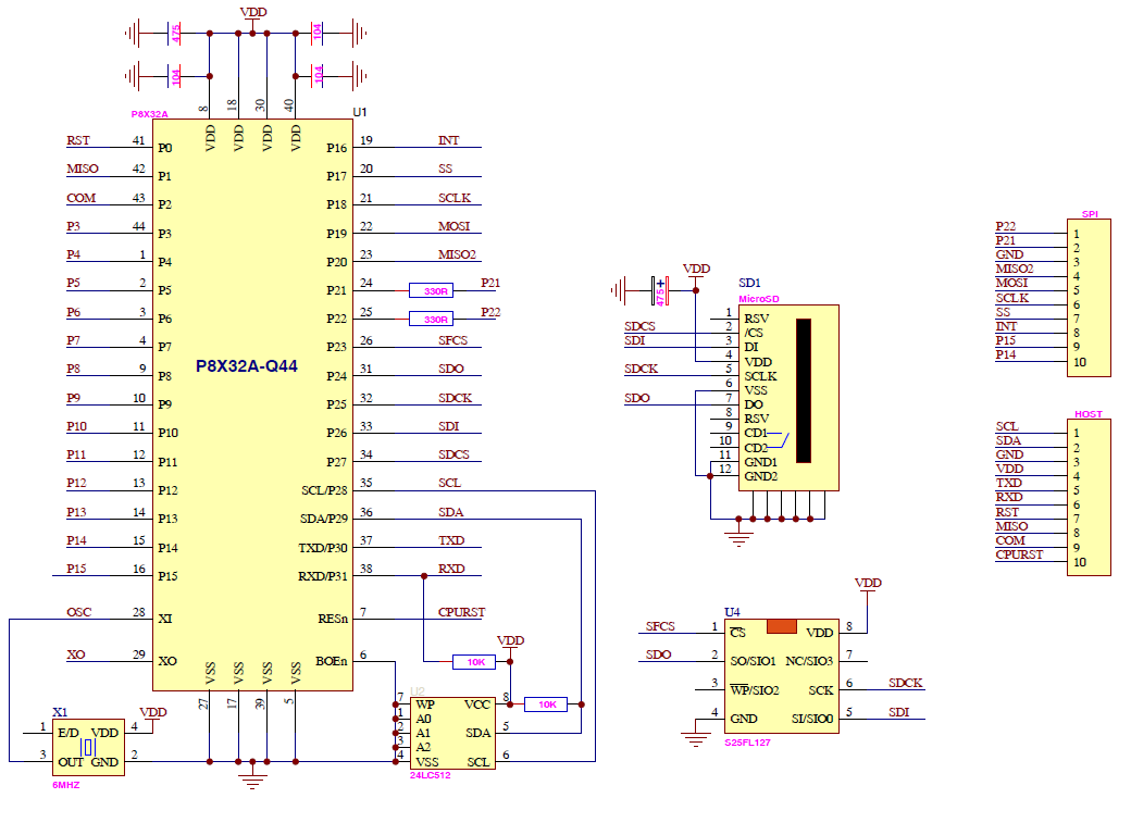
IoT5500 ETHERNET MODULE SCHEMATIC
+P8 CPU MODULE
The P8 CPU module can also be used as a standalone controller with 16 GPIO available on it's DIL header plus another 11 I/O off the fine-pitch edge connector. All that the module needs to operate is a 3.3V supply. Pin headers may be used to mount the module either way up or else it can be surface-mount soldered to the host board. It is also possible to surface-mount easily with a trimmed pcb to expose the half-holes.
+P8 CPU MODULE GENERAL PINOUT
|