
Heat Measurement with the
HUG Concentric Tube Calorimeter
Paul Hunt - Owner, Electrical Wizard
Ryan Hunt - R&D Manager
Hunt Utilities Group LLC
Pine River, MN USA
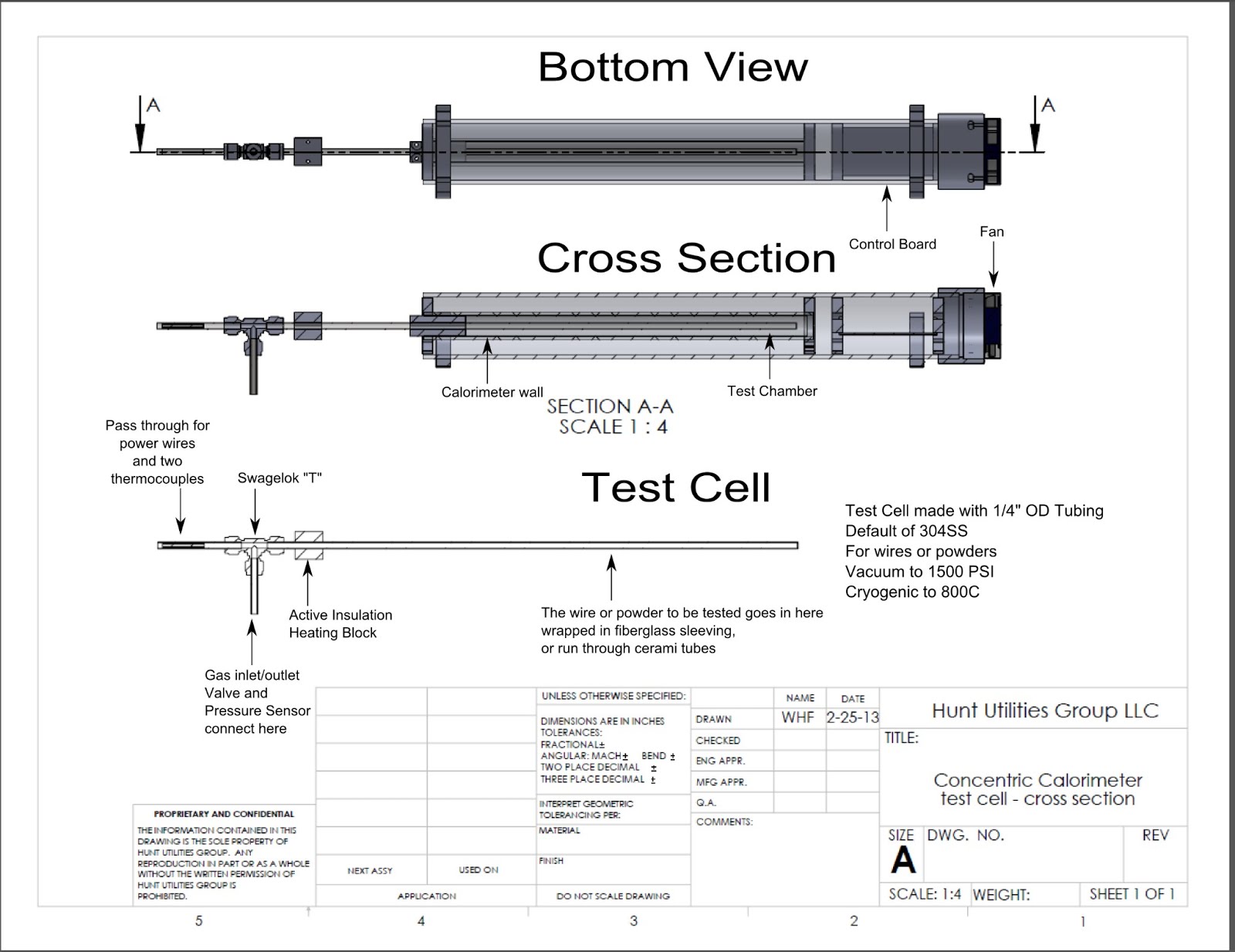
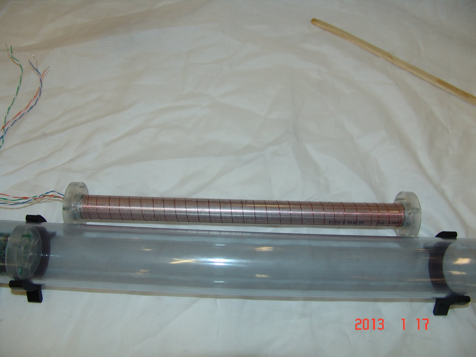
Figure 1
Theory of Operation
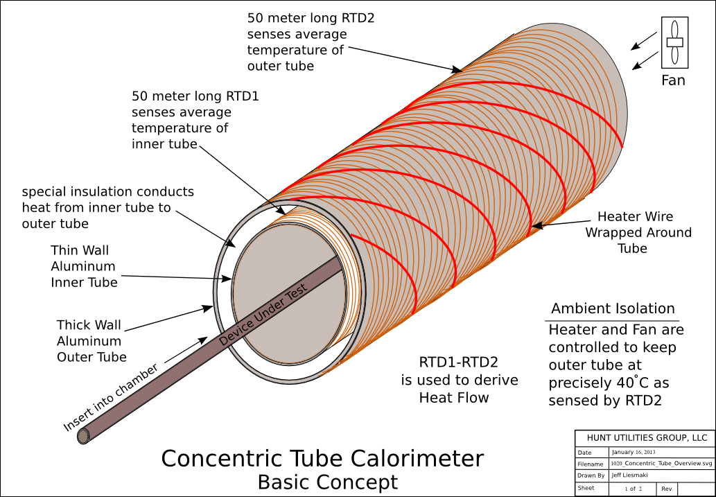
The inner tube forms the test chamber. The device to be measured is inserted into the center of the inner tube. The RTD wrapped around the inner tube senses the average temperature of the inner tube. The outer RTD senses temperature of the outer tube. For ambient control, a heater wire is wrapped around the outer RTD tube and it is controlled along with a small fan that blows ambient air over the outer RTD tube to keep the outer tube at precisely 40 degrees C. This, in effect, isolates the system from ambient temperature changes.
All heat generated in the test chamber has only a few ways to exit the chamber. By far, the largest heat flow is through the wall of the inner tube, through the thin insulation, and through the wall of the outer tube. The temperature difference between the inner and outer tubes is proportional to the heat flow in watts.
Very little heat flows out the closed end of the chamber because it is insulated with about 40mm of silicone foam.
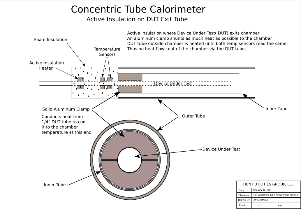
The Device Under Test (DUT) is a metal tube that protrudes from the open end of the chamber. To prevent heat from flowing out the DUT, first we use an aluminum plug to conduct as much of that heat as possible to the chamber wall, where it can be measured. That cools the DUT as it exits but it is still well above ambient. To prevent any heat flow out the DUT, we actively heat the DUT until there is no temperature drop along its length.
Construction
The concentric tube calorimeter is constructed from a thin wall aluminum inner tube approximately 19mm (.75 inches) diameter placed inside a larger heavier wall aluminum tube. An RTD wire made up of two strands of #40 copper magnet wire is wound around the inner aluminum tube.
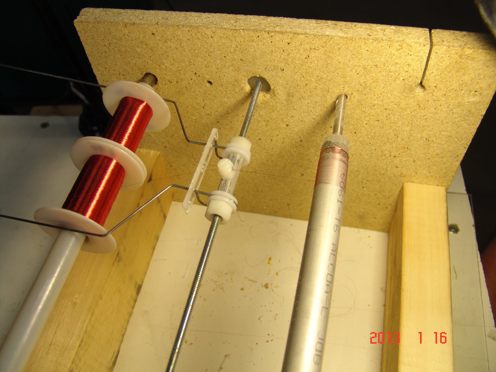
Figure 2: winding jig
Next, a fiberglass cloth and reflective foil around the inner tube forms the resistance to heat flow between the tubes.
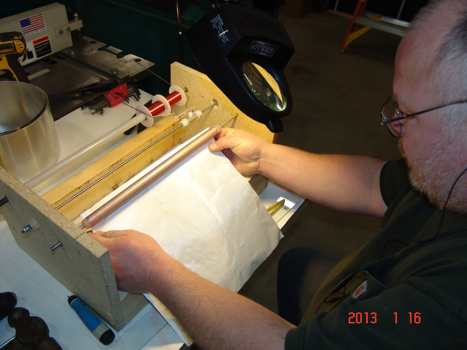
Figure 3: winding insulation.
The inner tube and insulation are inserted into the larger heavier walled outer tube.
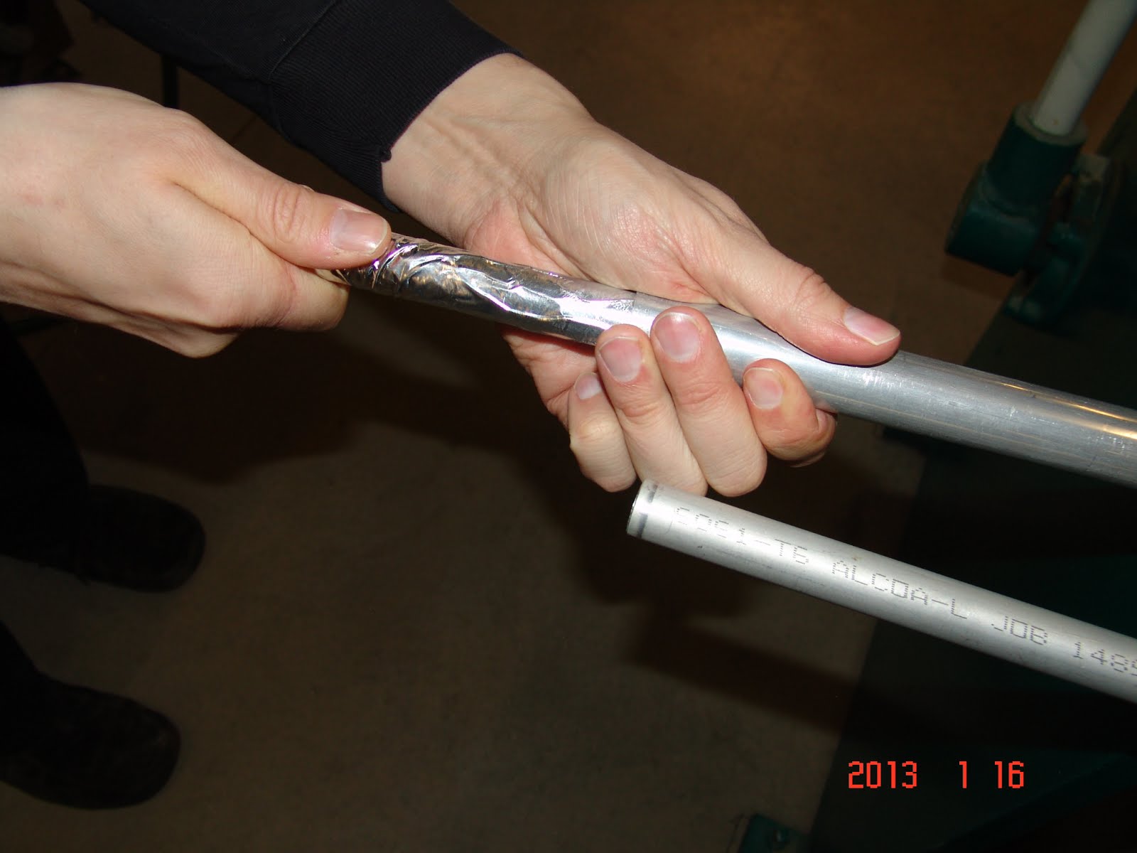
Figure 4
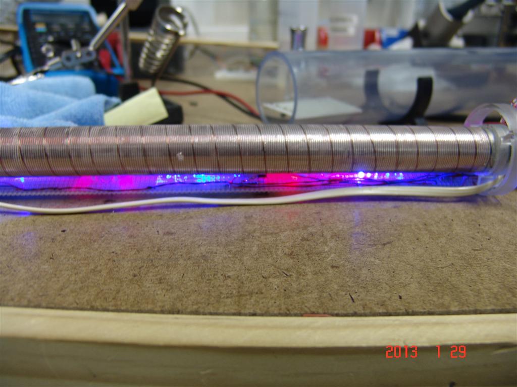
RTD wire is then wrapped around the outer tube and then a heater wire is wrapped around the tube over that. The wires wrapped around each tube are dual coils - one going each way - to eliminate noise from magnetic fields.
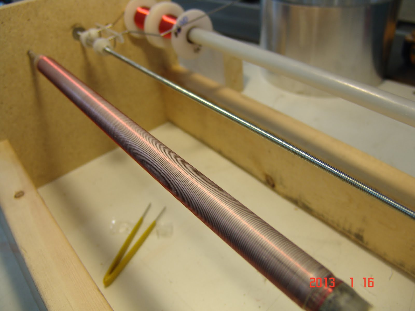
Figure 5: winding the outer tube
Supports milled from clear polycarbonate plastic are attached to the ends of the calorimeter along with a small circular circuit board necessary for electrical connections.
Figure 6
Figure 7
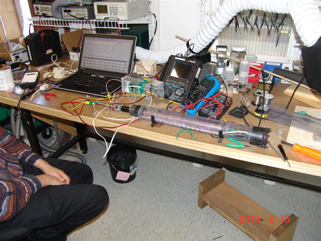
A surrounding chamber is then constructed from 2” Schedule 40 clear PVC. The small fan is mounted on one end along with supports and a HUGnetLab board for measurement and control (see Figure 8).
Figure 8
The unit is then assembled and ready for wiring and testing.
Figure 9
Added a circuit board and LED indicators for troubleshooting and easy performance indication.
And drilled holes to draw the air more smoothly over the length of the outer tube - visible in this picture.
Test Chamber Assembly
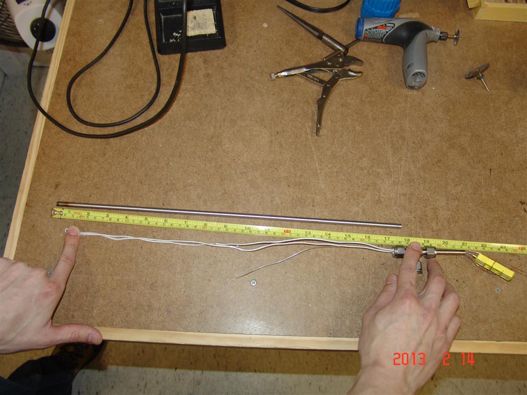
Assembled first joule heating element in the anticipated form factor for LENR tests. This test chamber is made from a ¼ inch Stainless Steel tube about 20 inches long and welded closed on one end. The other end plugs into a Swagelok “T”. The electrical connections (24 gauge copper conductors) and up to two stainless clad 0.020 inch diameter thermocouples are sealed into a short length of tube on the opposite end of the “T”. The third port of the T is the gas/vacuum connection. The wire leads and wires under test are clad with woven fiberglass wire insulation, or run inside ceramic tubes.
This first heater unit has approx 45 cm of 30 gauge NiChrome wire within the last 25 cm of the stainless tube.
More info on test cell assembly in this document.
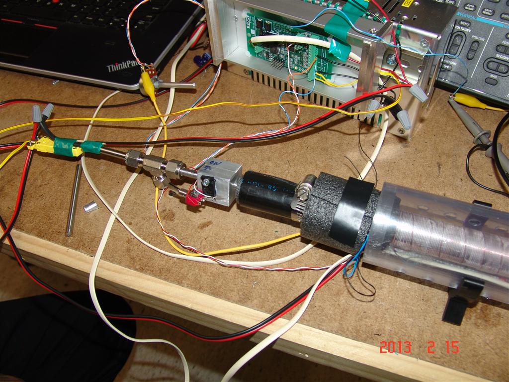
Added active insulation on the ¼” stainless steel tube protruding from the test chamber to eliminate all heat loss from that path. Then added insulation around those sensors. This is performing well,
Control strategy
- Hold the external tube at a constant temperature (30 to 40C) using the same full length temperature sensor that is used for the calorimetry measurement
- Add heat to heater wire if necessary
- Pull ambient air past it to cool it, if necessary
- PWM PID control for both of those - with LED indicators
3 PIDs -
- Active insulation - to maintain zero temperature gradient along the protruding part of the actual test cell.
- Outer Tube Heating Element - to maintain the outer tube at a constant temperature
- Fan - to maintain outer tube tube temperature when it needs cooling
- Active Insulation Heater
Calibration process
Calibrations were run with the 1/4” SS tube reactor. There were 4 total calibrations, the first three used a NiCr wire and the last calibration used the oxide coated ISOTAN44. The first three calibrations took place on 3/12/2013, 3/15/2013 and 3/18/2013. The last calibration was done after a month of downtime for the CTC on 4/17/2013.
The heater wire (NiCr and Ox) was put through steps, from 0 to 32 Watts in increments of 3, of power. The settling time was 1.5 hours. For each calibration the difference between the outside tube voltage and the inside tube voltage was recorded and then averaged between all 4 calibrations. We then correlated the input power to the difference in the voltage to create a calibration curve. This curve will be used in an active run to find an output power from the difference in voltage between the inner and outer tube.
Calibration results
Average | Oxide Wire – 16.5 in, 7.1 ohms | |||||
Input Power | Difference Average | St Dev | CI 95% | mV/Watt | CI 95% (W) | T_Heater (°C) |
0.00 | 0.0021 | 3.38E-05 | 5.38E-05 | 3.78E+01 | 0.0000 | 45.66 |
2.99 | 0.0002 | 2.43E-05 | 3.87E-05 | 6.75E-05 | 0.5729 | 113.00 |
6.00 | -0.0016 | 1.45E-05 | 2.31E-05 | 2.69E-04 | 0.0859 | 165.99 |
9.00 | -0.0034 | 7.42E-06 | 1.18E-05 | 3.76E-04 | 0.0314 | 213.08 |
11.98 | -0.0051 | 1.10E-05 | 1.75E-05 | 4.25E-04 | 0.0412 | 255.63 |
15.02 | -0.0068 | 1.81E-05 | 2.88E-05 | 4.53E-04 | 0.0636 | 297.16 |
18.01 | -0.0085 | 1.88E-05 | 2.99E-05 | 4.70E-04 | 0.0637 | 336.68 |
21.03 | -0.0101 | 1.42E-05 | 2.25E-05 | 4.80E-04 | 0.0470 | 369.61 |
23.98 | -0.0117 | 1.43E-05 | 2.28E-05 | 4.86E-04 | 0.0469 | 403.22 |
27.02 | -0.0132 | 3.23E-05 | 5.13E-05 | 4.90E-04 | 0.1048 | 438.96 |
28.99 | -0.0142 | 4.95E-05 | 7.88E-05 | 4.90E-04 | 0.1609 | 459.70 |
31.97 | -0.0156 | 1.40E-04 | 2.22E-04 | 4.88E-04 | 0.4559 | 493.25 |
*We will call out operating range from 6 Watts to 24 Watts. The temperature of the heater used the Oxide wire in the fourth calibration.
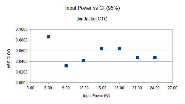
* The input power vs 95% CI as Wattage in our working range (6-24 Watts)
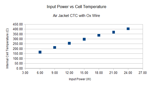
*The input power vs the internal cell temperature. This used the Oxide coated ISOTAN44.
Measured Resolution
In our working range we have a measured resolution between +/-0.031 W and +/-0.086 W
Preliminary assessment by Paul Hunt (2-19-13):
“It is interesting to look at temperatures under a microscope.
The concentric calorimeter currently is being tested with a cell that has a nichrome heater wire in it. The test heater is providing its own microsteps.
All evening the heater resistance has been slowly climbing. The voltage is as steady as a rock, so the power has been slowly going down. We can speculate what reactions are causing the wire to chemically change, thus raising the resistance by micro ohms per hour.
At about 20:15 the resistance suddenly dropped. The power went up by about 17mW. The calorimeter dutifully tracked the change.
The strange part is... even though the power went up and the inner tube temperature went up, the heater temperature sensor went down by an almost equal amount (.012 degrees)
The calorimeter has been consistently running anywhere from 14 to 37 milliwatts low. Tracking with about 18mW of p-p noise (using 5 minute averaging)
If a warm body walks into the room and sits next to it, The calorimeter drifts about 10mW.
My current estimate of all causes uncertainty without special care is about 50 milli-Watts.
With special care we can resolve about 2 milli-Watts “
Specifications
Test chamber length …............................................................... 0.335 meters
Test chamber diameter......................................................... 0.012 meters
Maximum Watts Expected in Chamber …................................................. 40 Watts
Inner Tube Temperature Rise ….......................................................... about 50. C
Outer Tube Temperature Setting …................................................. 40 degrees C
Inner Tube Maximum Temperature Expected …..................... about 90 degrees C
Air Gap Between Inner and Outer Tubes …............................ 0.635 millimeters
Tube material....................................................................................... Aluminum
Insulation material............Four layers of fiberglass cloth with aluminum reflectors.
RTDs made of 40 gauge enameled copper wound non inductively
RTD resistance.................................................................. about 150 ohms each.
RTD bridge excitation voltage................................................................. 2.5 volts
RTD bridge output voltage......... about 1 volt above negative excitation potential.
RTD bridge temperature sensitivity.................................... about 1 millivolt per C.
Heater Number of turns …................................................................... 66
Heater Wire Total Resistance …................................................ 7.2 Ohms
Heater Current (Maximum) ….................................................... 1.8 Amps
Heater Voltage (Maximum) ….................................................... 12 Volts
Heater Power (Maximum) …...................................................... 20 Watts
Next Generation:
We have already begun building the next generation. Some improvements include:
- Heavy copper inner tube to spread heat more evenly.
- More careful termination of tube closed ends to measure heat more evenly.
- Water jacket over outer tube. Flowing water keeps temperature constant along length of tube.
- Printed circuit board the full length of calorimeter makes the whole unit far more integrated and robust.
- Better package integrity should make it even more immune to ambient changes.