.:.:-- TACHYON --:.:.
Revised February 2020 for V5.7 kernel
Tachyon - A Forth "with a difference" for the Parallax "P1" 8-core microcontroller.
Extending the kernel - loading EXTEND.fth (or not)
Teaching Forth to learn new words
The ubiquitous BLINKY - an example
Extending Tachyon Forth and the EEPROM
PRONOUNCING FORTH WORDS & SYMBOLS
BACK TO THE CLASSROOM (and take up "SPACE")
SERIAL TERMINAL and INTERACTIVE ENTRY
PLAY TIME - Strings and things
INTRODUCTION

There are many books and sources with information about Forth but this short introduction is designed to give you a quick insight into how to make it work if you have loaded TACHYON onto a Propeller. Remember that Forth is not just a language, it's an environment or even the O/S if you like as it provides the interactive program development that is normally the preserve of the PC. Of course in our minimal systems we may have a serial connection to a PC but we are only using it for its storage, editing and serial terminal capability much like we would use a VGA monitor and keyboard and SD card for this very thing.
For the moment though we are just going to go through the steps to either download the binary or compile from the latest source. What's the difference? Well the binary is very handy if you happen to have a system that matches it, in this case we are looking at the basic Prop configuration which is based on a 5MHz crystal, VGA connections on pin group 16 and a 115200 baud serial link which most Terminal emulation program can handle (or should). Talking about terminal emulation then it is preferable if you happen to have an ANSI compatible terminal program such as Teraterm for Windows users or I have found Minicom to be excellent for Linux. Mac users will probably know and recommend some equivalent I guess. When I say ANSI compatible this refers to the handling of special control sequences to get the screen to position the cursor, change colors etc. Sometimes these ANSI terminals are referred to by their ancient hardware brands such as VT100 series etc. Propeller Serial Terminal will work in some respects but not for for pasting or sending files.
Extending the kernel - loading EXTEND.fth (or not)
Assuming then that we have a terminal which is all we really need to get started and of course the Spin tool to at least download the binary in the first place. If you are on Linux I recommend using minicom and BST and you can leave the terminal open but disconnected using ctrl P while downloading from BST. If you are familiar with downloading to a Propeller then do so. If your system uses a 5Mhz or 10Mhz crystal there is no need to change anything other than perhaps the default baud rate of 115200. All the configuration information is located right at the start of the file.
Alternatively you can download a precompiled image from this folder which includes EXTEND and EASYFILE.
QUICK LINKS
Once compiled and download into EEPROM with an F11 connect (or reconnect) the terminal and set it for 115200 baud 8N1 and soft or no handshaking. Also set the line delay to at 15ms (TeraTerm alt+S,E,msec/line or Minicom ^A,T,D). Now either reset the Propeller or send a "break" which will also accomplish the same thing or even typing <ctrl> C. There is no real need to do this though but it's good to see for the first time the startup message etc.
Propeller .:.:--TACHYON--:.:. Forth V5r4 NEON 540180811.0000
Cold start - no user code - setting defaults
--------------------------------------------------------------------------------
...
At this stage the Forth system should respond to text input but its vocabulary is still basic with all the high level extensions being contained in a separate file EXTEND.FTH, and this should really be loaded next into Tachyon itself before we do anything else. (Unless you are using the precompiled binary)
If you open EXTEND.FTH in a text editor you can select all and copy, and paste into the terminal. During the paste operation the echoing of characters will be suppressed and line numbers will represent where it is up to although it will not indicate line numbers for comment blocks. At the end of loading the system automatically reboots, starts up a background timer task, and displays the latest stats.
Now hit <enter> or <cr> as it is also referred to and the system should respond with an "ok" prompt in the new style with line number and current code pointer. The prompt in parentheses is also useful for showing what is user input and what is system response which is shown without the prompt.
... ok
What is happening is that Forth is waiting not just for your commands but is in fact an interactive compiler and interpreter so that you can say "go fetch" and if you have defined what "go" does and what "fetch" does then it will do it. Talking about defining let's look at a very simple example as if we were sitting at the terminal now. I want Forth to understand that when I say STAR that I want it to display a star (or asterisk) on the terminal. Follow along now as we show what happens while the terminal output is shown in a fixed space font with user input (you/me) in red to highlight what we type (followed by an "Enter">).
... STAR ???
Teaching Forth to learn new words
Obviously it doesn't know what STAR is then, we will have to teach it.
... : STAR '*' EMIT ;
... STAR * ok
We define a new word by entering a COLON and then the name of the definition followed by the code and terminated by a SEMI-COLON. Make sure you have a space or spaces between "words" which include the colon and semicolon. The name is entered into the "dictionary" of words and this word is linked to the code which in this case simply says - Push the literal for an ASCII * onto the stack (think of a coin going into a spring loaded coin clip, the first one in is also the last one out and they go in and out only from the top. So top of the stack is the equivalent for this ASCII value which in TACHYON is conveniently abbreviated like it should be as '*' but in practically every other Forth you have to know the value of this character which by the way is $2A and this could have been entered also. Next instruction is EMIT which is responsible for sending a character out to the terminal (or other device) and this character is always passed on top of the stack (think RPN). So once EMIT grabs the value to send out it has removed (popped) it off the stack and whatever was under it will now be popped on top etc. There is one instruction left which many programmers will be familiar with and that is RETURN from where it was called from, in this case the Forth terminal input. So the SEMICOLON is not actually compiled but is an instruction that gets executed immediately and compiles an EXIT which is what a RETURN in Forth is called and the SEMICOLON also completes the definition. Noticed what happened when we typed STAR <enter> in that it now knows about STAR and proceeds to execute the instructions so that we end up with a * on the screen.
That's a bit boring but let's expand upon that by making it print many stars depending upon the number we tell it.
... : STARS FOR STAR NEXT ;
... 8 STARS ******** ok
Just like we defined STAR so we add a new word to the dictionary and define what it does, in this case it implicitly calls our previous word STAR within a FOR...NEXT loop. But how many times does it loop? Remember the stack? All we need to do is leave a number on top of the stack which FOR will grab and use as the loop counter as shown.
The number 8 is recognized as a valid number and it gets pushed onto the stack just waiting for something to happen. STARS happily obliges as it needs a number which FOR grabs. So the loop is executed while NEXT will count down the 8 each time and keep looping back to anything between it and FOR until the count reaches zero after which it will exit the loop and EXIT or return back.
Before we move on we are going to do one more thing because as you have seen we can teach Forth new words and then we can also build those new words into other new words. Here's where we can go one step further where I returns the current loop index which by default starts at 0.
... 10 FOR CR I STARS NEXT
*
*
**
***
****
*****
******
*******
********
********* ok
Figure this one out for yourselves and also know that unlike most Forth implementations Tachyon allows looping and branching interactively outside of a definition because it compiles as you type word by word. This is also why you won't be able to backspace past the current word although if you do get messed up you can just hit the Esc key to discard the line.
Exercise: enter 4 BY before the previous example
4 BY 10 FOR CR I STARS NEXT
If you want to keep any settings or code in memory between resets then just type BACKUP and wait a few seconds as the system saves everything to EEPROM.
Try some more things interactively such as:
0 100 DUMP or WORDS or WWORDS or 12 34 + .
The period or full stop symbol is not the end of a line, it is a traditional Forth word and is used to pop a number from the stack and print it but PRINT is also included as an alias .
The ubiquitous BLINKY - an example
Not very exciting but how would you do this in Forth, especially Tachyon? First we need to hook-up an LED to a port pin, in this case I happen to have one on P4 that turns on when the pin is high. Many boards have an LED hookup, so find the port number it is on, I am going to "talk" to it directly like this:
4 HIGH ok
As soon as the <cr> is hit the code is executed in interactive mode. Now turn it off (assuming LED tied to ground through a resistor).
4 LOW ok
To make an LED flash we also need a delay between turning it on and off (and back on again), this is where we use the ms word (milliseconds) and combine all these elements into code:
: BLINKY 10 FOR 4 HIGH 100 ms 4 LOW 100 ms NEXT ; ok
Typing in BLINKY at any time now will execute the definition and make the LED flash on for 100ms and off for 100ms ten times.
Analysing what we just did with spaces between all numbers and words:
: | Create a new definition - name follows |
BLINKY | The name of the definition - any combination of letters, numbers, symbols, except space. |
10 FOR | Setup a loop from here for 10 times with a default step of 1 |
4 HIGH | Set PIN 4 to high |
100 ms | delay for 100 ms |
4 LOW | Clear PIN 4 to low |
100 ms | delay 100 ms |
NEXT | Countdown NEXT loop back to 4 HIGH |
; | EXIT return from definition |
Why not say LOW(4) instead? Well Forth as a complete language and environment on the Prop itself is possible because it keeps things simple so it uses postfix RPN (reverse Polish notation). Instead of typing delay.ms(100) we simply say 100 ms which is what we are thinking but the first method is what many who have programmed in other languages are familiar with, but they aren't natural anyway. If you care to remember, they took some getting used to at first.
Instead of saying 3*(4+7) we just say 3 4 7 + * and each number is processed and pushed onto a "last in, first out" stack so that + pops and adds the last two numbers 4 and 7 and pushes the result onto the stack, now the stack has 3 and 11 then the * pops those two numbers and pushes the result as 33 onto the stack. To see that the result use the number print word, either PRINT or just a dot symbol:
3 4 7 + * . 33 ok
Obviously if you were going to add two and then multiply them you would have written this as 4 7 + 3 * instead.
NOTE: If you want this to run in the background see the MULTI-TASKING section (but later). There is also a much simpler way to blink an LED without any software by using a counter. This happens to be built into Tachyon and I could just as simply have typed "4 BLINK" and the LED on P4 would blink 5 times a second without any further software or you could type 5 HZ to change it to 5 times a second.
STACKS
Traditional (boring) Forths only have a parameter (data) stack and a return stack. In these systems the return stack is used for loop parameters as well as data at times, doesn't that make you cringe thinking what would happen if that junk got left on there when it tried to execute a return?. There is no reason though why we just can't have more stacks, is there? So Tachyon has three stacks, the data and return stack as normal plus a loop stack just for loop parameters (index,count,step,branch) where branch holds loop branch addresses. All these stacks are in cog memory so they are limited in size but they are fast.
The data stack is made up of 4 registers in cog RAM (fast access) and a deeper stack also in cog RAM but not directly addressable. Well I (still) say, small is beautiful plus we need to be practical if we want speed and taking into account the Propeller's architecture. Remember though that there are other cogs just begging for a task, so in like manner as we would say to our trusty dog (or is that cog) "go fetch".
From a Propeller 1 PASM perspective the top 4 parameters of the data stack are very easy to access as stack items are in fixed locations and can be referenced directly without any calculations necessary. This equates both to speed and compactness. So the top of datastack or TOS is always in a fixed location as are the next 3 parameters. The same goes for the loop stack which holds the levels count,index,step,branch used in looping as well as the previous index J.
Table: List of Stacks
STACK | LENGTH | NOTES |
DATA | 4 + 28 | Holds top four parameters in direct access fixed cog registers a non-addressable stack in COG RAM |
RETURN | 28 | Holds the return address of Forth implicit calls in cog memory. No stack pointer. |
LOOP | 1 + 8 sets | COUNT FOR, INDEX FROM, STEP BY, BRANCH TO in fixed cog registers plus stack in HUB RAM |
So there is the data stack but there are no traditional Forth words PICK and ROLL or directly readable stack pointer although it's not all bad news. In fact, the bad news is actually good news if you look at it from an efficiency point of view. There are words to directly access the third and fourth items on the stack with 3RD and 4TH which work in the same way as DUP and OVER. In fact DUP and OVER could be thought of as 1ST and 2ND but we won't go there. At a higher level there is support for local variables which remove the stack entries and push them into a locals stack situated in hub RAM although this method is rarely used.
The Tachyon stack philosophy is to keep it simple, clean, and fast and parameters are normally capped at four with many of the more cumbersome stack operations being held in cog registers and directly operated on by the VM instructions. Have a look at the code for a lot of the .fth source files and you can see how much cleaner it looks in the way it handles parameters. Anyway, who likes trying to keep track of more than three or four stack parameters when coding? Learn to factor definitions so that the name of each factor describes what it does in a succinct manner, avoid long names which besides take up memory.
Here's a tip from the book "Thinking Forth" p199
Simplify code by using the stack. But don’t stack too deeply within any single definition. Redesign, or, as a last resort, use a named variable. |
INPUT NUMBER FORMATS
Just a short word too about the number formats we have been using in the examples. In some they are just plain numbers and in others they have attached symbols. Many programmers will be familiar with this notation that overrides any current number base default and forces the number to be recognized as decimal, hex, octal, binary etc. As well the default base (radix) is normally decimal but can be set directly or with predefined words such as HEX DECIMAL BINARY. The list below gives a quick overview through examples:
.
This is the best way to handle this, by using notations to denote the number base (although it is recommended to leave decimal numbers plain) :
$10 10 + DECIMAL . 26 ok
$10 #10 + DECIMAL . 26 ok
$10 #10 + HEX . 1A ok
^C . 3 ok
'0' 9 + . 39 ok
The last line (and before it) was a special case, it's another shortcut to make it easier for us to enter character or control literals. If you wanted to see what the full range of printable ASCII characters are we could type in a quick one-liner:
... $20 FROM 96 FOR I EMIT NEXT !"#$%&'()*+,-./0123456789:;<=>?@ABCDEFGHIJKLMNOPQRSTUVWXYZ[\]
^_`abcdefghijklmnopqrstuvwxyz{|}~ ok
Prefix symbols are preferred in Tachyon because the compiler will recognize these and try to process them first rather than going through the much longer cycle of searching the dictionary before trying to convert it to a number. In fact in V4 any character that is a digit is used to build a number in case it is a number which is much faster than converting it after a word is processed. You can also mix any non-numeric character you like in with the numbers to make it more readable so 80,000,000 for the clock frequency or #P26 for port 26 etc as long as the last character is a decimal digit.
There is no need to prefix the digits 0 to 9 as they will always resolve to the same value so just use these as plain digits. So the current convention is to leave the base in decimal and not to prefix decimal numbers unless necessary or desired.
Fast Literals
V5 uses 16-bit wordcode but only 15-bits are used for cog or hub code addresses with so with the msb set these 15-bits can represent a literal number from 0 to 32767. Literals that are greater than this are either compiled as opcode+16-bits or opcode+32-bits. A special case is -1 which is used quite often and has its own opcode (otherwise it would require 6 bytes instead of 2).
Table: RADIX SYMBOLS
PREFIX | USE | DEC | NOTES |
% | %10 | 2 | BINARY base 2 number |
# | #10 | 10 | DECIMAL base 10 number |
$ | $10 | 16 | HEX base 16 number |
& | &192.168.0.1 | - | IP notation, each decimal group is one of four bytes that make a long |
' | 'C' | 67 | ASCII character literal |
^ | ^C | 3 | ASCII control character literal |
INPUT OUTPUT
Hooking up a Propeller chip to the real world means we need a way to talk to the I/O ports which are really just another location in each cog's memory. They are in a region called the Special Purpose Registers or SPRs. Each cog has it's own set meaning that each cog has it's own pin direction register and output register as well as 2 counter/timers (A&B) plus the video registers. There are 32 I/O lines on the Propeller and each cog has access to them in identical manner with outputs being OR'ed together so that it is not possible for outputs to "fight" each other with one cog trying to force an output high while another tries to force it low etc. This also means that if one cog has left the pin high then it will appear to be stuck high from another cog.
TACHYON has support in the VM kernel as well as a few high-level bytecode instructions etc. With these instructions we can fetch and store to the ports, set or clear outputs, clock data in and out, or wait for edge transitions etc.
BIT BASHING A PIN
HIGH ( pin# -- )
Set the output port and direction register
LOW ( pin# -- )
Clear the output port and set the direction register
BIT BASHING PINS
OUTSET ( iomask -- )
Make the specified pins outputs and set them high
OUTCLR ( iomask -- )
Make the specified pins outputs and set them low
OUT ( state pinmask -- )
Set the output(s) to the value of state
P@ ( -- 32bits )
Fetch the contents of INA (Rarely used method)
P! ( 32bits -- )
Store to OUTA (Rarely used method)
SERIAL PERIPHERAL INTERFACE
SPIWR ( n -- n2 )
Write the top 8 bits of n to the SPI pins returning with n rotated left 8 places (i.e. $12345678 --> $34567812 )
SPIWRB ( byte -- byte )
Left justify and write a byte to the SPI pins
SPIWR16 ( word -- word )
Left justify and write 16-bits to the SPI pins
SPIWR32 ( long -- long )
Write 32-bits to the SPI pins.
SPIRD ( n1 -- n1n2 )
Read from SPI into LSBs of n rotating the existing data left (i.e. $12345678 --> $345678XX )
OUTPUTS ( iomask -- )
Make the specified pins outputs without touching the OUTA register
INPUTS ( iomask -- )
Make the specified pins inputs
WAITLO ( reg4 = mask : reg1 = CNT )
Essentially this instruction will wait until the input specified in reg4 goes low if a single I/O has been specified or any input low if multiple I/O lines are specified. Be aware that there is no timeout and if incorrectly set will appear to be "stuck". The mask needs to be written to reg4 in the cog using "4 COG!".
WAITHI ( reg4 = mask : reg2 = CNT )
Wait all the port lines are high
SHRINP ( iomask dat -- iomask dat*2 )
From a single bit to 32 bits of data may be shifted in with this instruction called from an external loop which is also responsible for the timing. The data can be right justified after all the needed bits are shifted in by performing a SHR to the correct place.
Used in: SERIN, I2C@
SHROUT ( iomask dat -- iomask dat/2 )
Primarily designed to shift data out a bit at a time while maintaining the modified stack parameters as pushing and popping slow things down. Since it is a shift right it will send LSB first so to send MSB first you must use a REV instruction to flip it around correctly.
Used in: SEROUT, I2C!
CLOCK ( cogreg4=iomask )
Toggle multiple bits on the output specified by COGREG4
PIN@ ( pin# -- state )
Read the state of the pin
PINS@ ( pin# pins -- val )
Read the pins starting from pin# and right justify and mask
Usage:
#P16 4 PINS@ \ read P16..P19 and return with value in $00..$0F
IN ( pinmask -- state )
Read the state of the input(s)
PIN! ( state pin# -- )
I2C BUS FUN
If you don't know what the I2C bus is then here's a very quick introduction and reasons why you would want to use it. I2C bus was originally invented by Philips to cut down their wiring between ICs in their TV chassis of the early 1980's. So it was originally referred to as the Inter IC bus but trademarked as I2C for licensing reasons I guess. Like SPI it uses clocked serial data to cut down on the number of lines needed to communicate with a chip such as a TV tuner or OSD chip etc. However SPI chips require 2 to 3 lines for clock, data in, data out plus one chip-select line per chip which in a system with 8 chips means that 11 I/O lines would be consumed or else decoder hardware is required.
The I2C bus is different in that it requires only 2 lines that are common to all chips without the use of individual chip selects. Instead the address of the chip is sent serially and through the use of special line conditions called START and STOP (in I2C speak) are able to communicate with a great number of chips. Think of a start condition (SDA high to low while SCL is high) followed by a device address as the equivalent of asserting a dedicated chip select, except you have the equivalent of 128 of them.
For us it is normal to have at least an I2C EEPROM chip available on a "bit-bashed" I2C bus on P28 and P29. Even though these port pins could be used for other things it is far easier to leave them as they are and run other I2C bus chips off these same two lines. There is seemingly no end to the variety of I2C chips available and besides EEPROMs there are other useful chips such as Real Time Clocks, Analog to Digital Converters, Digital to Analog Converters, I/O ports display drivers, accelerometers, sensors etc.
Now type lsi2c which is a word simply for us humans to be able to see if there is anything on the I2C bus that responds:
... lsi2c
*** I2C ***
A0 EEPROM
AE RTC EEPROM
40 I/O EXPANDER
DE MCP79410
The EEPROM has responded at address A0 while another device has responded at address AE as well as 40 and DE. In this case the device is the MCP79410 RTC which also has EEPROM and SRAM on my pcb. There are special words just for the Propeller's EEPROM, some are just for us to play with as we develop code and others are meant to be the interface to the EEPROM from runtime programs.
Type $7FE0 $20 EE DUMP and note that all the bytes are zero which is correct as the Spin tool erases the whole first 32K of EEPROM when it loads in new code. Now change a single location like this:
12 $7FE0 EC! ok
Now dump out this area again in the same manner as before and notice that the first location has been changed. It's that easy. To write a value to a memory location in Forth it is necessary to supply the address and the data and both of these items are passed on the datastack of course. Even though serial EEPROM is very very different from onboard RAM it is still memory and we can treat it as such, even assigning similar access words so that instead of @ and ! (pronounced fetch and store) we are using words named as EC@ and EC! to help us to see that these words do the same thing from our point of view. Likewise EC@ is equivalent to C@ (C fetch) which fetches a character or byte from memory so we could type:
$7FE0 EC@ . 12 ok
You can type in words from the terminal to directly manipulate the I2C bus and devices, let's try this:
<I2C $A0 I2C! $7F I2C! $E0 I2C! <I2C $A1 I2C! nakI2C@ . 12 ok
It's good to know that you can access hardware very easily without restriction, it's a really great debugging and development tool. In the interactive one-liner we were able to issue a START condition (<I2C), an 8-bit device address $A0, two bytes of memory address $7F $E0, then reSTART and get the EEPROM to read out the data it has there. If we were reading multiple bytes the I2C device needs to know when we are done reading bytes so what we need to do is issue a dummy read and not acknowledge the data (nakI2C@ vs ackI2C@) we have just read before issuing a STOP or another START like this:
nakI2C@ I2C> ok
Extending Tachyon Forth and the EEPROM
The EXTEND.FTH file and the BACKUP word was mentioned previously but you can continue to download other source code files in a similar manner such as EASYFILE.FTH etc and run BACKUP if necessary when you are done. There is no need to worry about "wearing out" the EEPROM as they are guaranteed for at least a million writes which even if you backed up 100 times a day every day for 10 years you still have another 20 years to go before you approach the minimum that the manufacturer will guarantee and it may take another 30 years before you see any failures. Of course you are more likely to wear out far before any of that happens! I've personally hammered one device and gave up after 10 million writes. So, don't even worry about it, not even for a microsecond.
Another thing that happens when you run backup is that you lock in your settings too such as your number base, some may prefer having the system reset into hex rather than decimal, that's your choice.
REDIRECTING OUTPUT
Normally the character output from Tachyon is through the serial link to the terminal but all character I/O is channeled through the word EMIT which is in itself revectorable. What does that mean? That just means we can point it somewhere else rather than at the default serial output. For instance say we connect an LCD display and write some code to interface to it, then wouldn't it be nice to be able to redirect the normal output from Tachyon through to the LCD instead? Of course, then words that print strings and numbers can be used in exactly the same way as they are used normally rather than duplicating and having special methods for each and every I/O device. How do we do this then?
Imagine we have connected a serial LCD on P6 that runs at 9600 baud. The code for this is very simple (vertical comments):
--- Define an EMIT for the LCD which sets the baud rate and then redirects output to SEROUT on P6
pub SERLCD 9600 SERBAUD EMIT: 6 SEROUT ;
Now in your code you can easily direct output to the LCD or any other device in a similar manner:
SERLCD CR PRINT" LCD printing" CON CR PRINT" Serial console "
THE DICTIONARY
Forth may be the only "language" that refers to its instructions and commands etc as a dictionary, why is that? Remember the introductory code example called STAR ? Well the very first thing we typed into the terminal was the word STAR which Tachyon didn't know about at all. But like an electronic dictionary where we can tell it to accept the new word and define it, likewise in a similar way we add "words" to the Forth "dictionary". It's easy to find out what's in the dictionary as there is usually a command for doing so. Of course such commands are of no use to run-time code but they are useful for us poor humans sitting at the terminal wondering what's going on. This is what makes Forth friendly as a target environment.
The normal word to use to list out the dictionary is WORDS but to keep it compact we will list it in another form with WORDS
... WORDS
DICTIONARY WORDS @5A5E
!LCD LCD LCDBL CHARLCD KEYPAD KEYPAD@ !KEYPAD KEYMUTE KEYBEEP BEEPER ANYKEYS !VGA VGA VCHAR PLOT VXY HUE rows cols screen VGAPIN @VP VGATEXT QV FL SA
VETEXT FRUN .FILES .FX .FILE lss VOLNAME! ls .LIST (SLIST) DIR .FNAME cd cd$ pwd cat (cat) FPRINT$ FLOAD FCOPY FCOPY$ RENAME RENAME$ APPEND -FERASE FM
AKE$ FOPEN FOPEN$ mk RW RO FOPEN# FCREATE$ MAKE FCLOSE >FILE FILE> FPUTB FPUT FGET FREM fwrite fread FSTAMP DIR? FSIZE! UpdateDir OpenDir FILE$ ?MOUNT
MOUNT ROOT FMAX@ CLUST>SECT @FAT @BOOT @ROOT FS FS@ FSW@ FSC@ FS! FSC! FSADR SD XW@ XC! XC@ X! X@ XADR FSECT@ FSIZE@ FSIZE dirbuf dirfsa @FILE FILE#
FILE SECTOR SCAN! FLUSH WRSECT SDWR !SD ACMD CMD SDPINS SDERR SDBUSY SDIO32 SDIO8 CARD? sdbuf _sdpins ocr csd cid #files BLKSIZ @rest EASYFILE SAVEROM
DEFAULTS .TIMERS .TASKS .INDEX HELP WWORDS .VARS ?? lsini lsroms .LAP ~F .FREQ .AUTO .INTERCOM .MODULES NEON lsi2c lsio TOOLS BOOT DEFER FSQRT FSIN F
/ F* F- F+ F> >F FCMD LOADCOGS LOADCOG DEGREES SERVOS PWM! PWM PWM% PWM.START RGBS RGB ALED RGBPIN IR.NEC .DHT DHT DISTANCE PING ID! INTERCOM! +POLL ?
POLL TIMERJOB !RTC .TEMP 'F 'C STAMP@ .DT TZ tz$ .ASMONTH .DATE .TIME .DAY DAY DAY@ SUN SAT FRI THU WED TUE MON DATE! SDT! DT! TIME! DATE@ HMS TIME@ D
EC>BCD BCD>DEC WRRTC RDRTC RTC RTC@ RTC! SETRTC runtime WATCHDOG ALARM: TIMEOUT? ALARM COUNTUP TIMEOUT timers TIMER AUTORUN IO! IO@ CONBAUD BACKUP ?BA
CKUP EE ECOPY EFILL ELOAD ESAVE ESAVEB ep I2CPINS EEPROM E! E@ EW@ EW! EC@ EC! EERD @EEWAIT @EE eeadr I2C400 I2C100 I2CFAST nakI2C@ I2C@ ackI2C@ I2C!
I2C!? I2C> <I2C> <I2C ?I2C i2cflg MODPINS SETPINS SPIPINS @SPISCK @SCL @CNT @CE @MISO @MOSI @SCK *SDA *SCL BLINK RINGS RING SIREN WARBLE BIP BEEPS TON
E BEEP CLICK SPKR MUTE HZ KHZ MHZ VOLTS FRQ DAC! BPIN APIN PLLDIV PLL DUTY DIFF CTRMODE NCO B A SERIN ISERIAL SERIAL ISEROUT SEROUT SERBAUD TRAP +VECT
OR REVECTOR (FORGET) FORGET RECLAIM STRIP !INITS +INIT INIT .CFA .HEAD$ ?ANSI MARGINS WRAP BOLD REVERSE PLAIN CURSOR ERLINE ERSCN CLS XY PAPER PEN HOM
E ESC white cyan magenta blue yellow green red black .BIN32 .BIN16 PRINT& .DEC2. .DEC2 .DECL .DEC4 .AS" .AS COGINIT TASKREGS RUN: RUN TASK? RND PINS@
OUT PIN! CNT? =CNT CNT@ P! P@ VSCL VCFG PHSB PHSA FRQB FRQA CTRB CTRA DIRB DIRA OUTB OUTA INB INA CNT PAR SPR LEFT$ RIGHT$ MID$ +CHAR $! APPEND$ $= LO
CATE$ NULL$ ESC? CON] CON [CON boot NULLOUT EMIT: KEY: M MB KB 1M s us ms FORK R@ INVERT MOD 2OVER 3DUP 2SWAP D. @. => <= AVG C~~ W~~ ~~ W>L B>L B>W W
>B L>W >W 3++ 3@ 3! @3 2++ 2@ 2! @2 C-- C++ W-- W++ -- ++ FALSE TRUE |< ] =[ SWITCHES CASES BREAK CASE SWITCH@ SWITCH STRING TABLE |<= WRAP DS DS+ reg
clong cword cbytes CARRAY CREATE DOES> SHORTCUT QUIET NUM>STR NUMBER .W: .W LIMIT >| WW! BIG! BIG@ U@ U! CLKMHZ CLKFREQ PUBLIC PRIVATE EXTEND " ." PR
INT" := vars org @org byte word long bytes words longs , || | C, W, L, ALIAS : pre pub pri module ; [C] ' ['] NFA' NFA, NFA$ NOP DUP 2DUP OVER DROP 2D
ROP SWAP ROT -ROT NIP 3DROP ?DUP 3RD 4TH >R R> !RP !SP AND ANDN OR XOR ROL ROR SHR >> 8>> SHL << 8<< 2/ 2* 4* SAR SPLIT9 REV MASK >b >N >B 0= NOT 1+ 1
- + - OVER+ 2+ CELL+ 2- * UM* U/ U/MOD / */ UM*/ IF ELSE THEN ENDIF BEGIN UNTIL AGAIN WHILE REPEAT FROM BY FOR NEXT LOOP I+ I J K LEAVE FOR@ FOR! BY!
LP! LP@ IC! IC@ C@ W@ @ C+! C! C@++ W+! W! +! ! D@ D! TX! 1! 1@ 1++ C~ W~ ~ BIT? SET? SET CLR TOG BIT! CMOVE <CMOVE ERASE FILL RESET 0EXIT EXIT ?EXIT
CALL JUMP ?JUMP WAITLO WAITHI RUNMOD (EMIT) (EMITX) LOADMOD COG@ COG! COGSTOP pCOGINIT COGID REBOOT CLK CLKSET WAITX WAITCNT LAP LAP@ CLOCK CLKIN CLKO
UT H L P T F SHROUT SHRINP OUTSET OUTCLR OUTPUTS INPUTS HIGH LOW FLOAT PIN@ IN SPIWRB SPIWR16 SPIWR32 SPIWR SPIRD SPICE 0<> <> WITHIN U> = > < U< 0< E
MIT SPACE SPACES CR KEY WKEY (KEY) KEY! doKEY CLS EMITS DOT BELL <CR> TAB TABS XTAB SPINNER .HEX .BYTE .WORD .LONG .WORD$ @PAD HOLD >CHAR ASCBIN #> <#
# #S <D> PRINT$ CTYPE .NFA LEN$ U. .DP PRINT . CREATE: CREATE$ GETWORD SEARCH CFA CPA +NFA NFA ALIGNORG ALIGN @NAMES names WORDS ALLOT ALLOCATED HERE
[W] [B] ["] KEY$ [W,] VER .VER TACHYON END CONSOLE ECHO DISCARD TASK REG BUFFERS COLD HEX DECIMAL BINARY RAM DUMP: DUMPX DUMP DUMPW DUMPL DUMPC DUMPA
DUMPAW QD DEPTH .S DEBUG .STATS IDLE NOOP --- \ '' ( { } IFDEF IFNDEF OFF ON GRAB ABS ?NEGATE NEGATE MIN MAX MINS MAXS ADDABS SUBABS CMPSUB UM/DMOD U
M/MOD WAITVID [WS2812] [SDRDF] [SDRD] [SDWR] [SDIO] [SSD!] [PWM32] [PWM32!] [PLOT] [ROL3] [CAP] [WAV] [MCP32] [RCTIME] errors uhere uthere flags promp
t uauto keypoll lastkey rxpars rx id keytable @WORD uemit ukey base num uswitch undef (.") (") ... V5 *end*
PRONOUNCING FORTH WORDS & SYMBOLS
If you want to be able to read Forth code you need to get into the habit of pronoucing all those symbols as if they were words. Take for instance the common symbol @ which is normally pronounced AT but in Forth this is FETCH. Likewise ! which is pronounced STORE so therefore when we read code that goes like this "var1 @ 10 + var1 !" we read it by pronouncing it this way "variable1 FETCH 10 PLUS variable1 STORE". Notice too the spacing as we read groups of words so that var @ are two words that will leave the value of var1 on the stack, then 10 + which adds 10 to that value, then var1 ! which then stores the value back to the variable. Of course in some other lex language you could say "var1 = var1+10" but in Forth not only can we treat it as any type we like (string,character,short,long etc) but there are better ways of doing simple things like this "10 var1 +!". So +! would be read as PLUS STORE with an implicit FETCH.
Many Forth words are short or use a symbol or two as opposed to PC-centric languages for good reason since Forth itself is usually implemented on and in a resource constrained embedded system where we interact with the language through a keyboard. Imagine if we have to type a long sentence with the correct syntax everytime we wanted to do something simple? Very frustrating and time consuming. Instead we can type "var1 @ ." to examine a variable or "100 var1 !" to set it etc. Some of those symbols don't show up well in proportional fonts so Tachyon also has aliases for many of these too such as PRINT for . and pub for : etc
( EDITING )
All the latest definitions that have been added to the PC compiled kernel are the very latest shown at the top of the listing.. Unlike most Forth systems which will normally store the name of a definition at the start of its code and gets referred to as "the HEADER", Tachyon Forth is done a bit differently to suit the Propeller. Why? One very obvious reason is that we have limited memory and the dictionary is not required to run the code, only to allow us humans to interact and to use Forth to compile more source through the terminal etc. So how does this save memory? Well it doesn't at this particular stage of development but the scheme is that the kernel part of the dictionary will reside in RAM where the image of the Tachyon kernel is which becomes reusable after booting.
Some of the words in the dictionary have been enclosed in parentheses which we just call brackets to denote that these words are not meant to be used interactively. If the names had simply been left out of the dictionary that would stop us trying to use them but brackets are the warning signs to remind us. They have been left in the dictionary so that they can be referred to if we are extending the "compiler" part of the Forth. Interestingly I sometimes refer to Tachyon and sometimes to Forth and sometimes to both. The reason is that Forth is built up on the Tachyon VM whose instruction set and architecture support Forth in the use of stack based operations. Getting back to this "compiler" part of Forth I am referring to the special words that create and modify new words and structures. We have already seen how to create a word using COLON and how to end it with SEMI-COLON. Both of these words are only ever used when compiling on the target, and to prevent some of these words being compiled themselves as would SEMI-COLON normally, the attributes for some words have an IMMEDIATE tag. If the parser finds the word and sees that it has an immediate tag then it will not compile it but execute it instead. So the ; word can say "compile an EXIT and finish off this definition ready to interact once again". Many other words are immediate such as DO LOOP IF THEN etc.
To find out a bit more about each word have a look at the source code documents (linked at the bottom of this page) which explain their usage a bit more.
PLAY TIME
Forth is about productivity and being hands on rather than spending too much time thinking how it should be, specifying, planning, designing and then finding out it won't work!
PING
So I want to construct a proximity alarm, one that will warn me as I get 1 metre or closer, so that as I get closer the beeps will be faster and higher in frequency. If I am outside that zone then it should be quite.
Therefore I hookup the ping sensor, this requires a trigger line and a echo receive line. These are the timing signals.
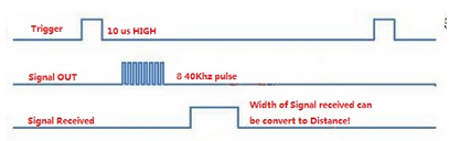
First we define these I/O lines that we need as constants and pass this to the PING routine to keep it general-purpose so we can use any I/O.
#P16 == TRIG --- high output to trigger ping
#P17 == ECHO --- signal received input, measure high time
Now we can create a general-purpose PING function that accepts the pins we want to use and returns with the time in microseconds.
pub PING ( trig echo -- us )
--- setup WAITPxx mask
MASK 4 COG!
--- 10us trigger (dummy cycles)
DUP HIGH 10 us LOW
--- detect high period
WAITHI WAITLO
--- calculate high period
1 COG@ 2 COG@ - ABS
--- convert cycles to us
CLKMHZ U/
;
Test that out:
TRIG ECHO PING . 6013 ok
So using the WAITHI WAITLO instructions we can measure the high period as they capture the CNT value when they are successful. Next step is to also convert this to distance using a simple formula for the speed of sound at 0.34029mm/us although we also divide by two because the of the time it takes to echo back. So multiply microseconds by 0.170145 to calculate distance in millimetres but how do we do this without floating point? Wot, no floating point? That's right, we could add it but it's not fast and since we normally know the range of the signals we are dealing with we just scale the figures up and down like this:
--- return with the range in mm using trig pin and echo pin
pub DISTANCE ( trig echo -- distance.mm ) PING 170145 1M */ ;
Test this too:
TRIG ECHO DISTANCE . 1023 ok
So you notice the multiply by 0.170145 was scaled up by 1,000,000 (1M is defined as a constant) to make it a whole integer and then scaled back down again with the magic of */ which uses a 64-bit intermediate result to maintain accuracy.
To generate audible tones we could feed into an amplified speaker but a piezo transducer is simpler and rather loud, especially if you drive it differentially, and especially if it hits a resonant frequency. There are words built into Tachyon to generate single-ended frequencies on any pin but we want something to generate a differential signal so we will create a new word called HZ2 that does just that
--- Generates a differential output frequency
pub HZ2 ( freq -- ) 5 CTRMODE HZCON #10000 */ FRQ ;
This still needs to know the A and B pins to output to but we will build that into the PROX word itself.
--- simple proximity alert
pub PROX
#P19 APIN #P20 BPIN --- setup piezo to be driven differentially
#P19 LOW #P20 LOW --- make both of them outputs
BEGIN
#P16 #P17 DISTANCE --- take a reading
DUP 1000 SWAP - 2* 0 MAX HZ2 --- generate a note that is inversely proportional to the distance of up to 1M
50 ms 0 HZ2 --- let it sound for a fixed interval
20 / 200 MIN ms --- but let the quite period (<200ms) get shorter the closer we get
ESC? UNTIL --- continue doing this until an ESCAPE key is pressed
;
Test this out now by typing PROX and when you get to within 1 metre it will start to sound with the closer you get causing it to squeal more.
BACK TO THE CLASSROOM (and take up "SPACE")
Space is nothing, it's just space butasyouknowwithoutitthenthingsbecomeabitdifficult. Point taken thank you, we must have one or more spaces between words in any language (except German I believe) to clearly see and understand the word. Forth requires this space too, for words, for numbers, for operators, etc. Each one is a distinct entity and must be treated as such. Take for example the way we might print a string in another language:
PRINT "HELLO THERE"
That's fine for that language which is going through rather complicated hoops and is very very particular about the syntax. You will never get a "SYNTAX ERROR" from Forth, it is free-form as long as each word is distinct. So look closely:
PRINT" HELLO THERE"
What's different here? The word is actually PRINT" not PRINT and there's a space between PRINT" and the string that follows and that is delimited by a matching " This is very important and in this case we only want a single space but it doesn't normally matter how many spaces and on which line as long as it all flows together. However try to make it readable, both to yourself and to others. For your information the PRINT" is a normal Forth word so it needs a whitespace after it but what it will do is it itself will compile immediately all the characters right up to the trailing " . This type of word which executes immediately rather than be compiled itself is called an immediate word but it doesn't actually print it out immediately, it only compiles the string properly ready to be executed.
Note: The normal Forth word for printing a literal string is ." but an alias has been created for this in the form of PRINT" and they both work exactly the same way, it's just that the PRINT" form is instantly recognizable, clearer to read in formatted documents and plus in Forth we have the freedom to tailor the language to suit.
BACKUP and AUTORUN
As mentioned earlier it is possible to run BACKUP to save your current Forth session but that also means all your variables and if you are using VGA then even the pixel buffer gets saved. The full 32K of RAM less the stuff we don't ever want changed such as the VM image etc but otherwise the whole shebang.
You can also run BACKUP or your own version of it from your user code whenever you need to make sure that things are backed up. The other way is to write a version of backup that compares RAM and EEPROM and only writes a page of 64 bytes if there is a difference. Beware though that EEPROM has a limited endurance for the number of times you can write to a location, in most cases it is at least 1 million times which is never ever a problem for when we are developing code and backing up. However if you are updating a variable that changes often then bear in mind not to exceed this limit. You can come very close to it as a minimum is a minimum and 1,000,000 writes/location is guaranteed to work.
Once you have tested out your little application you want it to be able to run "untethered" from the PC and survive power downs etc. So we have seen how BACKUP can save everything but we also need to tell it what to do on power-up. This is where the AUTORUN word comes in. All it does is find the address of the following word and if it is found it will set the "autovec" vector to this address. When Tachyon boots it goes into the TERMINAL definition and tidies up a couple of things before checking this "autovec" and if it is non-zero it will call the address that is stored there. Depending upon your software this may even return back to TERMINAL to continue with its interactive terminal. Supplying an invalid "command line" parameter or none at all will simply disable AUTORUN.
To test this all out we will use the PROX demo from earlier but this time we will make it run in it's own cog automatically at startup. Since we don't want it exiting we change the ESC? UNTIL into an AGAIN which will repeat without termination and also give it some stack space.
8 LONGS proxstk --- allocate room for 2 levels of the loop stack in hub ram
pub PROX
5 RUN: --- Run the following code in cog 5
proxstk LP! --- setup a loop stack for this Tachyon cog and init it
#P19 APIN #P20 BPIN --- setup piezo to be driven differentially
#P19 LOW #P20 LOW --- make both of them outputs
BEGIN
#P16 #P17 DISTANCE --- take a reading
DUP 1000 SWAP - 2* 0 MAX HZ2 --- generate a note that is inversely proportional to the distance of up to 1M
50 ms 0 HZ2 --- let it sound for a fixed interval
20 / 200 MIN ms --- but let the quite period get shorter the closer we get
AGAIN
;
Type ' PROX +INIT (don't miss that little tick symbol there) followed by a BACKUP then check it out by rebooting or even powering off and back on. The +INIT adds the code field address of PROX.boot to a table of other init code which is then scanned by BOOT (in EXTEND) which verifies that it seems valid and calls these inits.
Just to make it a bit easier I have just done a video showing how to compile from on-line source, load in the extensions and a demo program which I have setup to AUTORUN.
SERIAL TERMINAL and INTERACTIVE ENTRY
There's a lot of information to be gleaned by perusing the source code and a lot of this information could be put into a manual but sometimes we learn more by receiving the information as and when we need it. That way we connect because we have a need, we have relevant questions, and we can see how the answer fits in and most especially, the why.
Since hopefully you have been following these examples by interacting with your own Tachyon system we can just go over some commands you can use from the keyboard when you are entering into the default Forth terminal. Sometimes you start typing a line but you know that it's all wrong, I do it all the time. Now rather than backspacing all the way back just hit the "ESC" key which will scrub the line. Another useful control is ^X (control X) which will re-eXecute the previous line. ^C will reset Tachyon and ^D can be typed anytime to dump out some debugging details. You may also find that when you do backspace that it only goes as far as the current word before it beeps at you. The reason is that it has already compiled the previous words on the fly rather than waiting until the end of the whole line. Sometimes this could be viewed as a nuisance but an upshot of this is that it tells you if there is a problem as soon as you type in a wrong word with a "???" and you can continue then to type in the correct word. Here's a table of the control keys and their actions:
TERMINAL CONTROLS
--- BREAK Perform a reboot regardless of the state of the Tachyon kernel etc (initiated from the serial driver)
$00 ^@ NULL ignored, discarded
$03 ^C Reset Tachyon
$04 ^D Perform an immediate transparent debug dump
$09 ^I TAB Substitute with a space ($20)
$0A ^J LF ignored, discard
$0D ^M CR Terminate and accept line
$13 ^S Init stack
$17 ^W Words
$18 ^X reeXecute the previous line
$1B ^[ ESC Scrub the current line plus overwrite on the terminal with dashes
$20 SPC Accept the current word and try to compile it (or execute if it's a premptive word) - warn if there is a problem
$7C | Multi-line terminator for interactive input - moves to a new line but does not execute code
PLAY TIME - Strings and things
Strings are very useful, not only to tie up brown paper packages but also to string printable characters together, not only into words, phrases etc but also into structures to hold indexed labels for instance. Say we wanted to look at the SPRs inside the cog, how could we do that? Well there is the word for dumping cog memory that's very quick:
... $1F0 16 DUMPC
0000.01F0: 0000.1940 AB06.BF50 E00A.4018 0000.0000 7000.0000 0000.0000 4000.0000 0000.0000
0000.01F8: 0000.0000 0000.0000 0000.0000 0000.0000 0000.0000 0000.0000 0000.0000 0049.329C
Yes, that was quick but it's not very friendly at all, I have to go back to the Propeller manual and look up the names for each of these registers. Can't I get this Tachyon to do it for me? Sure, we could write a line of code for each of the 16 locations that would do a COG@ and label each line. But this is not "elegant", there should be some thought that goes into how to do it better, anyone can write spaghetti code.
My motto "No effort, no joy" is equally applicable when it comes down to little things like this. Remember that what we want to do then is to dump out the address of each register and its contents on each line and label it and the best way to dump it is from a loop, but we need a unique label for each line of the loop. One way to store the labels so that they are indexable is to concatenate them together with a fixed size per label, in this case four is sufficient. When we concatenate them or string them together we form a longer string (but no knots!). Typing in the names from the manual and making sure each one has four characters we end up with "PAR CNT INA INB OUTAOUTBDIRADIRBCTRACTRBFRQAFRQBPHSAPHSBVCFGVSCL". So how do we refer to and handle this in Forth? As in many languages strings are referred to by a pointer, that is the address in memory where the string starts. Typically strings are terminated with a null character which is universally accepted as a $00. Tachyon follows this method for terminating strings rather than the normal Forth method of preceding it with a count byte.
Back to our problem, all we need to do then is to know the address of the string and index into it every four characters to "find' the label that we want that corresponds to the SPR address. By the way, we are only concerned with the 16 SPR locations as an index, not its absolute address. In Forth strings are represented using the normal " characters except we place a single space after the leading " because " is actually a word that executes to compile all the characters up to the trailing " as a string. Simple huh? Yep! We could talk a lot more about what goes on under the hood but sufficient to say that when it's executed at runtime it will leave the address of the string on the stack. Have a look at how we can use this label string in a word that nicely dumps out the SPRs.
: SPRS \ Dump the cog's SPRs with labels
16 FOR CR I $1F0 + .WORD ." : "
I 2 << " PAR CNT INA INB OUTAOUTBDIRADIRBCTRACTRBFRQAFRQBPHSAPHSBVCFGVSCL" + 4 CTYPE
." = " I $1F0 + COG@ .LONG
NEXT
;
... SPRS
01F0: PAR = 0000.1940
01F1: CNT = 819F.A4C4
01F2: INA = E00A.4018
01F3: INB = 0000.0000
01F4: OUTA = 7000.0000
01F5: OUTB = 0000.0000
01F6: DIRA = 4000.0000
01F7: DIRB = 0000.0000
01F8: CTRA = 0000.0000
01F9: CTRB = 0000.0000
01FA: FRQA = 0000.0000
01FB: FRQB = 0000.0000
01FC: PHSA = 0000.0000
01FD: PHSB = 0000.0000
01FE: VCFG = 0000.0000
01FF: VSCL = 0049.329C
...
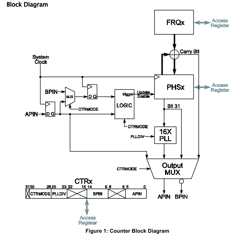
WARNING! INTERACTIVITY COUNTERS

How do you test out a new PCB or the peripheral chips, or special functions? Mostly this is not done easily as you read the manual (RTM), try to interpret what is being said and juggle this with any caveats and interactions, initializations etc. Since Forth is a development tool (not just a language) then let's put it to good use. I want to have a good look at the cog's CTR counters. What can I do with them, what happens if I change modes, the PLL divider, and combine another counter onto the same pin. These are just some questions I might come up with. Looking at the manual there are different bit fields for these controls so what I immediately want to do is to let Forth do the dirty work, I just want to be able to enter a value and some commands. So here's a few lines of Forth that take all the hard work out of interacting with the counters. The idea is that they will manipulate the bit fields for us while we work at a higher level but with direct contact with the "bare metal". Forth has been described as a "low-level" language and that's true, it is really low-level but what gets missed in categorizing a "language" is that it might fit into more than one category. Forth is both low-level and as high-level as you want it to be but most of the time we like to have the window down and hear and feel the engine revving and get the best gear change.
EXTEND is preloaded with many of the utilities and I/O words that you would use on the Propeller including many sensors.
The idea is that we can set up a counter and then change things on the fly, even in interactive loops while we observe what is happening. My observation involves both an audio transducer and an oscilloscope. To select CTRA I just type A which does not need to be typed in again unless I change to B. To produce a tone on pin 19 use the NCO mode so type:
A 4 CTRMODE #100,000 FRQ #19 APIN
To produce a beating tone I use CTRB and set it up in similar fashion except for a slightly different frequency:
B 4 CTRMODE #100,100 FRQ #19 APIN
Now it's no longer a pure tone, we can hear the beat. Going one step further to make the beat vary we can type in a one-liner loop:
BEGIN #90,000 #20,000 ADO I FRQ LOOP KEY? AND UNTIL
This sounds really scary, even though I know what's happening. Hitting any key will exit the loop but the counters are still running so just type:
OFF A CTR! OFF B CTR!
This does nothing more than clear the counters and in fact there is a word called MUTE that does this. To do this easily next time we can enter what we just did into a new word along with the predefined words in EXTEND.fth:
: UFO
A #100,000 FRQ #19 APIN
B #100,100 FRQ #19 APIN
BEGIN #90,000 #20,000 ADO I FRQ LOOP KEY? AND UNTIL
A MUTE B MUTE
;
Anytime you type in UFO you can spook out some unsuspecting person, especially if you have this amp'd!
Here's a quick routine to “see” the beat frequency using an LED, give it a study
: PULSELED ( ledpin -- )
DUP \ duplicate the ledpin, now we have two copies of ledpin on the stack
A APIN \ select ctra and assign ledpin to APIN, APIN word just consumed one copy of ledpin off stack right?
#1000 HZ \ start ctra in NCO mode at 1000 hz, see the EXTEND.fth source for HZ definition
B APIN \ select ctrb assign ledpin to APIN, note both items we had on the stack are now gone
#1001 HZ \ start ctrb at 1001 hz
;
You turn the counters off as before with A MUTE B MUTE
Loadable PASM modules
RUNMOD
RUNMOD is a instruction to run a PASM module which is loaded with LOADMOD. Rather than have one fixed SPI "instruction" taking up precious cog memory this area has been reserved for various loadable modules. Most of these modules are SPI'ish in nature but are optimzed for various devices such as SD memory, display controllers etc.
WS2812 ( addr cnt -- ) ( COGREGS: 4=txmask )
The WS2812 RGB LED driver will transmit the buffer specified using the output mask that is stored in COGREG4.
SPIO ( send -- receive ) ( COGREGS: 0=sck 1=mosi 2=miso 3=cnt 4=cs )
Enhanced Serial Peripheral Input Output
- Transfers 1 to 32 bits msb first
- Transmit data does not need to be left justified to be ready for transmission
- Receive data is in correct format
- Data is shifted in and out while the clock is low
- The clock is left low between transfers unless a chip select mask is specified
SSD ( send cnt -- ) ( COGREGS: 0=sck 1=mosi 2=miso 3=cnt 4=mode )
SSD module added for fast TFT DISPLAY SSD2119 SPI operations
SDRD ( dst cnt -- ;read block from SD into memory )
Reads in a block from the SD card - 512 bytes takes 1.44ms or 2.92us/byte
SDWR ( src cnt -- ;write block from memory to SD )
Write a block to the SD card
PLOT ( x y -- )
Plot a pixle in the pixel buffer
In addition to these PASM modules there are also ROMS which are binary images of PASM code that is loaded into a cog as needed. When we want VGA we need to load a cog up as the VGA engine while our application only needs to write to memory to change the display. There are many types of ROMs and they will discussed in a more advanced section.
MULTI-TASKING
The Tachyon console starts up in cog 0 while the serial receive driver takes over cog 1 and cog 2 runs the timer task. This leaves cogs 3 to 7 available so they are loaded with the VM kernel and told to wait for an assignment by running a loop called IDLE which monitors it's hub variable for something to do.
All we need to do is tell it what we want it to run so we don't have to do any coginits at all. Once it's running another task it's not possible to get it to change unless your code has instructions for it to check it's task variable. This is normally a good thing in a tested turnkey application but interactive development the only thing that will restore them is a reset.
RUN ( pfa cogid -- )
Runs a task in a cog from 2 to 7.
Example:
13 == RDYLED
: BLINKY BEGIN RDYLED HIGH 100 ms RDYLED LOW 100 ms AGAIN ;
' BLINKY 4 RUN
RUN: ( cog -- )
Run the code following this word as a task in designated cog.
Example:
: pri SENSORS 3 RUN: BEGIN 12 13 DISTANCE ' mm V! 15 DHT ' 'c V! ' rh V! 60 ms AGAIN ;
TASK? ( -- task )
Find the next available cog that's free to run a task (ready and in IDLE).
( To listen for a command )
ATN@ ( -- cmd )
Read in a command from the tasks variable and return with it and also clear the tasks variable
( To send a response )
ENQ! ( data -- )
( To talk to tasks in other cogs )
ATN! ( cmd cog -- )
( To listen to tasks in other cogs )
ENQ@ ( cog -- data )
To help you see what task are running just use the .TASKS word:
.TASKS
00: CONSOLE 0000 00 00 00 00 00 00
02: TIMERS 2D54 2D54 01 00 00 00 00 00
03: IDLE 0000 01 00 00 00 00 00
04: IDLE 0000 01 00 00 00 00 00
05: IDLE 0000 01 00 00 00 00 00
06: IDLE 0000 01 00 00 00 00 00
07: IDLE 0000 01 00 00 00 00 00 ok
If you are wondering what about TIMERS, it's part of EXTEND.FTH which maintains soft RTC timers which are useful for application timeouts etc and it's used by EASYFILE that way too. BTW, If your system has an I2C RTC you can tell Tachyon the I2C address and it will automatically write to it when you change the time and date, and also it will read it in at boot time to update the soft RTC. Then at the stroke of midnight it will reload its soft RTC from hardware just to keep things synchronized. If your RTC has an address of $DE (which shows up in lsi2c or ??) use $DE SETRTC then BACKUP. It will automatically read this on the next boot or when it thinks it is midnight.
DS3231 DS1307 MCP79410 PCF8563 | $D0 $D0 $DE $2A2 |
TIMERS
Now that we have mentioned TIMERS, let's have a look at how we can use it. First off, the TIMERS task maintains a chain of user specified 32-bit countdown timers in software which are decremented down to zero every millisecond. If the timer is zero then nothing happens. A countdown is useful because it times out and a check can be made to see if it has reached zero and timed out. If your application starts a motor which normally only stops once it has engaged a home switch for instance then it might not stop if that sensor is faulty, this is where you need a timeout to check for faults.
To keep it simple consider this code which simply toggles an output for every time a button is pushed (or held).
TIMER mytimer
: RunStop
( Reload timer to check again in 100ms )
100 mytimer TIMEOUT
( is button pressed? )
1 PIN@ 0=
( then toggle LED on P0 )
IF 0 PIN@
IF 0 LOW ELSE 0 HIGH THEN
THEN
;
( During setup set alarm code )
' RunStop mytimer ALARM
( then trip with any timeout )
1 mytimer TIMEOUT
In setting up RunStop we assign an alarm to it and start it off with any value but 1 means it will trip and start running the RunStop in 1ms. Use a larger value if you want to hold it off if other code needs to setup too.
TIMER ( <name> -- )
Usage: TIMER mytimer
Creates a timer structure that the timer cog can link into and maintain. Four longs are allocated in data memory
TIMEOUT ( milliseconds timeraddr -- )
Usage: 1000 mytimer TIMEOUT (timeout in 1000ms)
As well as loading the specified timer with the timeout value this routine also checks to see if it needs to be linked into the chain of timers that are decremented every millisecond. The timeraddr points to 4 longs in memory that are normally created with the TIMER word and besides the 32-bit timer value it also has fields for an alarm vector, the link to the previous timer, and modes etc.
TIMEOUT? ( timeraddr -- flg )
Usage: mytimer TIMEOUT? IF ( do something maybe )
Sometimes rather than checking for a timeout you would like to do something automatically on a timeout. This is called an ALARM and the TIMERS cog can execute user specified code automatically upon timeout which could also include reloading the timer which is not automatic by design.
ALARM ( cfa timeraddr -- )
Usage: ' MYALARM mytimer ALARM
WATCHDOG ( ms -- )
One timer is preset with an alarm to reboot the Propeller but is only activated once user code triggers it using the WATCHDOG word.
TIMEOUT ALARM EXAMPLE
TIMER mytimer
: RunStop
( Reload timer to check again in 100ms )
100 mytimer TIMEOUT
( is button pressed? )
1 PIN@ 0=
( then toggle LED on P0 )
IF 0 PIN@
IF 0 LOW ELSE 0 HIGH THEN
THEN
;
( During setup set alarm code )
' RunStop mytimer ALARM
( then trip with any timeout )
1 mytimer TIMEOUT
A word of caution regarding the use of the ALARM as this is called from the TIMERTASK cog. First off, the word that is called should not stall the TIMERTASK process for more than one millisecond at the absolute maximum but preferably this word should take less than 100 us per timer which in Tachyon means there is plenty of time to get things done. Also, since each cog has its own direction registers this should be taken into account as to which cog has control of certain I/O pins. It may be necessary with shared I/O to leave lines low or as inputs so that any cog can still drive it high etc.
To check which timers are running:
... .TIMERS ticks = 1/1,000 runtime = 7,356
768C: mytimer 768C 9ms =0000.0007 L7558 ALARM=RunStop 3F1E
7558: wdt 7558 0ms =0000.0000 L0001 ALARM=REBOOT 0254 ok
KEYPOLL
Maybe you don't need a regular timeout, you just want to check things in the background in which case you can just tie in with keypoll so that while the Tachyon cog is waiting for KEY input it will run a few errands for you.
keypoll ( -- waddr )
Adddress of ow-priority task that is polledwhile waiting for a key in the same cog.
Not quite multitasking but if all you want is a lazy background poll that occurs when the console isn't busy then you can use keypoll so named because while it's waiting for a KEY or character input it will happily execute a background function.
Example:
: BLINKER
CNT@ 8 REG @ CLKFREQ 10d / + > '' 100 ms or more ?
IF CNT@ 8 REG ! '' reset for next match
RDYLED IN 0= RDYLED OUT '' toggle the LED
THEN
;
' BLINKER keypoll W! '' run the blinking LED in the background
SD CARD
If your system has an SD card connected to any pins then you can load EASYFILE to access the SD card memory blocks directly and also as FAT32.
2C00 80 SD DUMP
0000_2C00: EB 58 90 6D 6B 64 6F 73 66 73 00 00 02 08 20 00 .X.mkdosfs.... .
0000_2C10: 02 00 00 00 00 F8 00 00 10 00 04 00 00 00 00 00 ................
0000_2C20: F0 87 3B 00 E0 0E 00 00 00 00 00 00 02 00 00 00 ..;.............
0000_2C30: 01 00 06 00 00 00 00 00 00 00 00 00 00 00 00 00 ................
0000_2C40: 00 00 29 03 06 CB EB 4E 65 77 20 56 6F 6C 75 6D ..)....New Volum
0000_2C50: 65 20 46 41 54 33 32 20 20 20 0E 1F BE 77 7C AC e FAT32 ...w|.
0000_2C60: 22 C0 74 0B 56 B4 0E BB 07 00 CD 10 5E EB F0 32 ".t.V.......^..2
0000_2C70: E4 CD 16 CD 19 EB FE 54 68 69 73 20 69 73 20 6E .......This is n
!SD ( -- )
Initialize the SD card interface to get it ready for reading and writing.
EASYFILE
FAT32 layers for virtual memory access of up to 4 open files at a time.
FILE ( file# -- )
Select a file slot from 0 to 3 for 4 independant files
FOPEN ( <name> -- )
Open up the file and store the virtual address
FSC@ ( fsaddr -- byte )
Read a byte offset from the start of the open file.
FSC! ( byte fsaddr -- )
Write a byte offset from the start of the open file.
.FILE
List the currently selected file slot
Examples:
FOPEN LOGON.HTM...opened at 0000.4022 ok
.FILE
#1 LOGON .HTM .....a 0000.4022 Jun 15 2014 15:44 0,388 ok
FILE@ $80 SD DUMP
0080_4400: 48 54 54 50 2F 31 2E 31 20 34 30 31 20 55 6E 61 HTTP/1.1 401 Una
0080_4410: 75 74 68 6F 72 69 7A 65 64 0D 0A 53 65 72 76 65 uthorized..Serve
0080_4420: 72 3A 20 54 41 43 48 59 4F 4E 0D 0A 44 61 74 65 r: TACHYON..Date
0080_4430: 3A 20 54 75 65 20 4A 61 6E 20 20 34 20 32 33 3A : Tue Jan 4 23:
0080_4440: 31 35 3A 34 38 20 32 30 30 30 0D 0A 57 57 57 2D 15:48 2000..WWW-
0080_4450: 41 75 74 68 65 6E 74 69 63 61 74 65 3A 20 42 61 Authenticate: Ba
0080_4460: 73 69 63 20 72 65 61 6C 6D 3D 22 54 61 63 68 79 sic realm="Tachy
0080_4470: 6F 6E 20 57 65 62 20 53 65 72 76 65 72 22 0D 0A on Web Server".. ok
HOW FAST DOES IT RUN?
There are two aspects to this question here, one from the kernel's perspective and the other from the user code perspective. There are many kernel instructions that execute in 400ns or so while some that have to wait their turn to access the hub may take over 1us. But we are probably more interested in the user code perspective and to help time operations there are two words LAP and .LAP which can be used interactively, let's see how by first checking the basics.
... LAP LAP .LAP 0 cycles = 0.000us ok
... LAP NOP LAP .LAP 32 cycles = 0.333us ok
On the first line we just double check that doing nothing between LAP & LAP is correct, then we do the next thing which is tell it to do the minimum, in this case a NOP instruction suffices. So the fastest instruction takes 333ns at 96MHz (6Mhz x16).
Pushing two numbers and adding them takes:
... LAP 4 8 + LAP .LAP 272 cycles = 2.833us ok
That might appear slow for an addition but let's just analyse what we just did. First off there is the time to stack two numbers and pushing and popping are slower operations in Tachyon when compared to operators.
... LAP 8 4 LAP .LAP 160 cycles = 1.666us ok
The reporting function does not bother to show you anything smaller than 0.1 microsecond resolutions, just to keep it simple. It takes 1.66us to stack two numbers and that's because it takes at least 400ns just to read each bytecode instruction and a good 600ns to push the parameter by moving all the other stack items. Now you know that pushing and popping is a relatively slow operation but still up there for speed.
We can put our code in a large loop to magnify the result but first we want to find out what the overhead of looping itself is:
... 1000 LAP FOR NEXT LAP .LAP 48,240 cycles = 502.500us ok
An empty loop takes 500ns with the other 2.5us the overhead of the FOR word (Actually FOR only takes 1.66us to stack 4 parameters!)
Coming back to our original test and adding a drop to prevent stack overflow and putting that in a loop:
... 1000 LAP FOR 8 4 + DROP NEXT LAP .LAP 400,240 cycles = 4.169ms ok
Gives us an adjusted result of XXXus for the "8 4 + DROP" sequence and XXXus of that is fetching the + instruction, adding the two stack parameters while dropping one parameter off the stack in the process after which the result itself is dropped..
For the BLINKY code we looked at earlier how fast can we toggle the outputs?
... 1000 LAP FOR 4 HIGH 4 LOW NEXT LAP .LAP
432240 cycles at 96MHz = 4.502ms
Or optimize it a little more by setting a mask and leaving it on the stack using the fast I/O words:
... 4 MASK 1000 LAP FOR T NEXT LAP .LAP
80240 cycles at 96MHz = 835.833us
Results in a >600kHz square wave and if we want to go faster there are other software optimizations without even touching the counters, of which we will discuss later.
MULTI CHANNEL PWM
Up to 32 PWM channels can run automatically from a dedicated cog using a table based approach. Each long in the table represents a sample of 32 ouptuts and there are 256 samples in the table representing a total of 8-bits. The PWM is updated at a maximum of 2Msps @ 80MHz resulting in an up to 7.8kHz PWM rate at 8-bits. Because a table is used it is also possible to shorten the cycle over fewer samples such as 128 or 64 etc and increase the PWM frequency while losing some resolution.
How to do it:
( STEP 1 - setup a table ) TABLE pwms 1024 BYTES \ allocate a 256 longs table for the PWM map ( STEP 2 -specify a frequency ) 7600 PWMFREQ \ Set the frequecy ( STEP 3 - specify the outputs and the address of the table and start the PWM cog ) \ Start up PWM using from P0..7, P16..P23 for 16 channels %00000110_00000000_11111111_11111111 pwms RUNPWM32 ( STEP 4 - set the duty cycle for indivdual pins or groups of pins ) 25 % 0 31 SETPWMS 10 #P4 SETPWM \ set P4 to 10/256 duty 50 % 2 SETPWM \ set P2 to 50 % duty 1 25 SETPWM 255 26 SETPWM |
SERVO FUN
A multi-channel servo driver is built into Tachyon, all you need to do to start using it is give it a cog to work in and it will handle the rest. To start up the task in cog 3: 3 RUNSERVOS
Now you can specify the angle in degrees and the port to use: 90 5 DEGREES
You can run almost as many servos as you like and you can even specify the timing pulse: 1720 20 SERVO!
- Tachyon Forth Resource Links -
Please email me for any suggestions, comments etc pbjtech@gmail.com