

DPDT Relay PC BoardMicroprocessor Controlled Relay
BASIC PC BOARD
Typical applications could include diode clipper or capacitor switching, signal routing or any other application that would require a dpdt toggle switch.
The microprocessor circuit draws slightly over 4 ma. at idle (LED off) with the current draw briefly rising when the switch is hit to toggle the relay. Except for the few milliseconds when the pulse is applied by the AVR, the relay is drawing no current.
The switching should be click-free, but it will really depnd on the dc levels at the points being switched. Note that the relay makes a very tiny "tick" sound inside the pedal when it actuates.
The pre-programmed AVR is included with purchase of the pc board. No special programming knowledge is needed; just solder in the micro and go. It is a CMOS chip so use appropriate handling and soldering techniques.
The relay board will blink the LED twice when it is initializing to let you know that it is working properly. The default is for switch pads 2 and 3 connected, and pads 4 and 5 connected.
The layout and use are exactly like a manual switch. Pads 1, 2, and 3 are always completely separate from 4, 5, and 6, just as with a manually operated dpdt switch.
CONNECTIONS
The L pad is the drive for the LED indicator.
A Ground pad is wired to the common ground point used by the fx circuit. I usually solder it to the ground lug on one of the signal jacks. There are two ground pads so that one can be used with the footswitch.
The 6 pads around the relay which are labeled 1 through 6 are the dpdt switched connections, as previously explained.
The Sw connection and the Gr (ground) next to it should be connected to the momentary footswitch. It can also be a panel (momentary) switch is the relay pcb is used in a rack mount chassis.
SWITCH
The switch mechanism can even be a mercury tilt switch, Hall sensor, photocell or any number of other types of devices that can pull the Sw pad connection to ground. Even a quick pulse from a microprocessor or CMOS circuit can trigger the relay circuit.
A momentary switch for use with the relay pcb is available on our Order Page.
ORDERING INFORMATION
|
 The AMZ DPDT relay pcb is a small (1" by 1") circuit board that contains an AVR microprocessor and a latching relay, which can be used with a soft-touch momentary switch to add switching to a new effects build, or even retrofit into an existing pedal. With a jumper set on the pcb, it can even be used as a true bypass switch.
 A lot of work went into developing the assembly language code for the microprocessor, which includes switch debounce and noise immunity. The micro can also detect if you are holding the switch down, which it will ignore. There is even some code that makes sure that the LED status and relay position do not get out of sync.
 Pad 2 is the common connection for the left side of the relay switch and it toggles between connecting to 1 or 3. Pad 5 is the common connection for the right side of the relay switch and it toggles between connecting to 4 or 6.
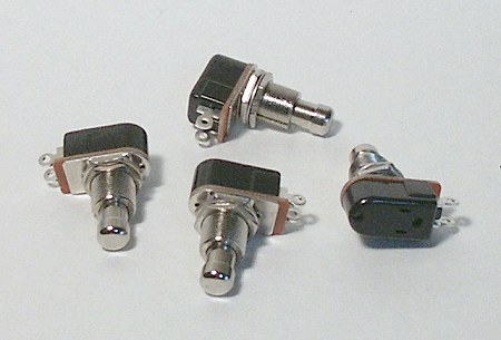 A heavy-duty momentary footswitch is recommended for this circuit. Suitable units are made by GC and CARLING (110-PM-OFF). If the switch is to be placed on a rack panel where it can be actuated by hand, numerous switches are available to do the job. All that is required is a momentary switch that is normally OFF.
AMZ-FX Home Page
Lab Notebook Main Page
Guitar Effects Blog
©2012 Jack Orman
All Rights Reserved